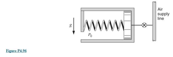
An insulated spring-loaded piston/cylinder device, shown in Fig. P4.96, is connected to an air line flowing air at 600 kPa and 700 K by a valve. Initially, the cylinder is empty and the spring force is zero. The valve is then opened until the cylinder pressure reaches 300 kPa. Noting that u 2 = u line + C v ( T 2 − T line ) and h line − u line = R T line find an expression for T, as a function of P,, P0, and T. With P 0 = l00 kPa , find T 2 .
An insulated spring-loaded piston/cylinder device, shown in Fig. P4.96, is connected to an air line flowing air at 600 kPa and 700 K by a valve. Initially, the cylinder is empty and the spring force is zero. The valve is then opened until the cylinder pressure reaches 300 kPa. Noting that u 2 = u line + C v ( T 2 − T line ) and h line − u line = R T line find an expression for T, as a function of P,, P0, and T. With P 0 = l00 kPa , find T 2 .
Solution Summary: The author evaluates the expression for T_2 as a function of the values of P1,p_0 and __-
An insulated spring-loaded piston/cylinder device, shown in Fig. P4.96, is connected to an air line flowing air at 600 kPa and 700 K by a valve. Initially, the cylinder is empty and the spring force is zero. The valve is then opened until the cylinder pressure reaches 300 kPa. Noting that
u
2
=
u
line
+
C
v
(
T
2
−
T
line
)
and
h
line
−
u
line
=
R
T
line
find an expression for T, as a function of P,, P0, and T. With
P
0
=
l00 kPa
, find
T
2
.
CORRECT AND DETAILED SOLUTION WITH FBD ONLY. I WILL UPVOTE THANK YOU. CORRECT ANSWER IS ALREADY PROVIDED. I REALLY NEED FBD.
The cantilevered spandrel beam shown whose depth tapers from d1 to d2, has a constant width of 120mm. It carries a triangularly distributed end reaction.Given: d1 = 600 mm, d2 = 120 mm, L = 1 m, w = 100 kN/m1. Calculate the maximum flexural stress at the support, in kN-m.2. Determine the distance (m), from the free end, of the section with maximum flexural stress.3. Determine the maximum flexural stress in the beam, in MPa.ANSWERS: (1) 4.630 MPa; (2) 905.8688 m; (3) 4.65 MPa
CORRECT AND DETAILED SOLUTION WITH FBD ONLY. I WILL UPVOTE THANK YOU. CORRECT ANSWER IS ALREADY PROVIDED. I REALLY NEED FBD
A concrete wall retains water as shown. Assume that the wall is fixed at the base. Given: H = 3 m, t = 0.5m, Concrete unit weight = 23 kN/m3Unit weight of water = 9.81 kN/m3(Hint: The pressure of water is linearly increasing from the surface to the bottom with intensity 9.81d.)1. Find the maximum compressive stress (MPa) at the base of the wall if the water reaches the top.2. If the maximum compressive stress at the base of the wall is not to exceed 0.40 MPa, what is the maximum allowable depth(m) of the water?3. If the tensile stress at the base is zero, what is the maximum allowable depth (m) of the water?ANSWERS: (1) 1.13 MPa, (2) 2.0 m, (3) 1.20 m
CORRECT AND DETAILED SOLUTION WITH FBD ONLY. I WILL UPVOTE THANK YOU. CORRECT ANSWER IS ALREADY PROVIDED. I NEED FBD
A short plate is attached to the center of the shaft as shown. The bottom of the shaft is fixed to the ground.Given: a = 75 mm, h = 125 mm, D = 38 mmP1 = 24 kN, P2 = 28 kN1. Calculate the maximum torsional stress in the shaft, in MPa.2. Calculate the maximum flexural stress in the shaft, in MPa.3. Calculate the maximum horizontal shear stress in the shaft, in MPa.ANSWERS: (1) 167.07 MPa; (2) 679.77 MPa; (3) 28.22 MPa
Need a deep-dive on the concept behind this application? Look no further. Learn more about this topic, mechanical-engineering and related others by exploring similar questions and additional content below.


 Elements Of ElectromagneticsMechanical EngineeringISBN:9780190698614Author:Sadiku, Matthew N. O.Publisher:Oxford University Press
 Mechanics of Materials (10th Edition)Mechanical EngineeringISBN:9780134319650Author:Russell C. HibbelerPublisher:PEARSON
 Thermodynamics: An Engineering ApproachMechanical EngineeringISBN:9781259822674Author:Yunus A. Cengel Dr., Michael A. BolesPublisher:McGraw-Hill Education
 Control Systems EngineeringMechanical EngineeringISBN:9781118170519Author:Norman S. NisePublisher:WILEY
 Mechanics of Materials (MindTap Course List)Mechanical EngineeringISBN:9781337093347Author:Barry J. Goodno, James M. GerePublisher:Cengage Learning
 Engineering Mechanics: StaticsMechanical EngineeringISBN:9781118807330Author:James L. Meriam, L. G. Kraige, J. N. BoltonPublisher:WILEY