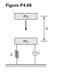
Figure P4.88 represents a drop forging process. The anvil mass is m 1 = 1000 kg, and the hammer mass is m 2 = 200 kg. The support stiffness is k = 107 N/m, and the damping constant is c = 1 N-s/rn. The anvil is at rest when the hammer is dropped from a height of h = 1 m. Obtain the expression for the displacement of the anvil as a function of time after the impact. Do this for two types of collisions: (a) an inelastic collision and (b) a perfectly elastic collision.
Figure P4.88 represents a drop forging process. The anvil mass is m 1 = 1000 kg, and the hammer mass is m 2 = 200 kg. The support stiffness is k = 107 N/m, and the damping constant is c = 1 N-s/rn. The anvil is at rest when the hammer is dropped from a height of h = 1 m. Obtain the expression for the displacement of the anvil as a function of time after the impact. Do this for two types of collisions: (a) an inelastic collision and (b) a perfectly elastic collision.
Figure P4.88 represents a drop forging process. The anvil mass is
m
1
=
1000
kg, and the hammer mass is
m
2
=
200
kg. The support stiffness is
k
=
107
N/m, and the damping constant is
c
=
1
N-s/rn. The anvil is at rest when the hammer is dropped from a height of
h
=
1
m. Obtain the expression for the displacement of the anvil as a function of time after the impact. Do this for two types of collisions: (a) an inelastic collision and (b) a perfectly elastic collision.
Find the equivalent mass of the rocker arm assembly with respect to the x coordinate.
k₁
mi
m2
k₁
2. Figure below shows a U-tube manometer open at both ends and containing a column of liquid
mercury of length l and specific weight y. Considering a small displacement x of the manometer
meniscus from its equilibrium position (or datum), determine the equivalent spring constant associated
with the restoring force.
Datum
Area, A
1. The consequences of a head-on collision of two automobiles can be studied by considering the
impact of the automobile on a barrier, as shown in figure below. Construct a mathematical model (i.e.,
draw the diagram) by considering the masses of the automobile body, engine, transmission, and
suspension and the elasticity of the bumpers, radiator, sheet metal body, driveline, and engine
mounts.
Need a deep-dive on the concept behind this application? Look no further. Learn more about this topic, mechanical-engineering and related others by exploring similar questions and additional content below.
EVERYTHING on Axial Loading Normal Stress in 10 MINUTES - Mechanics of Materials; Author: Less Boring Lectures;https://www.youtube.com/watch?v=jQ-fNqZWrNg;License: Standard YouTube License, CC-BY


 Elements Of ElectromagneticsMechanical EngineeringISBN:9780190698614Author:Sadiku, Matthew N. O.Publisher:Oxford University Press
 Mechanics of Materials (10th Edition)Mechanical EngineeringISBN:9780134319650Author:Russell C. HibbelerPublisher:PEARSON
 Thermodynamics: An Engineering ApproachMechanical EngineeringISBN:9781259822674Author:Yunus A. Cengel Dr., Michael A. BolesPublisher:McGraw-Hill Education
 Control Systems EngineeringMechanical EngineeringISBN:9781118170519Author:Norman S. NisePublisher:WILEY
 Mechanics of Materials (MindTap Course List)Mechanical EngineeringISBN:9781337093347Author:Barry J. Goodno, James M. GerePublisher:Cengage Learning
 Engineering Mechanics: StaticsMechanical EngineeringISBN:9781118807330Author:James L. Meriam, L. G. Kraige, J. N. BoltonPublisher:WILEY