
EBK SYSTEM DYNAMICS
3rd Edition
ISBN: 9780100254961
Author: Palm
Publisher: YUZU
expand_more
expand_more
format_list_bulleted
Concept explainers
Videos
Textbook Question
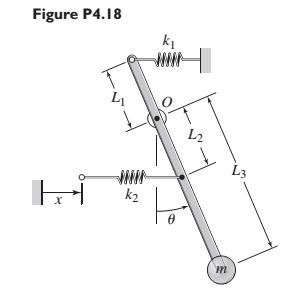
Chapter 4, Problem 4.18P
The mass m in Figure P4.18 is attached to a rigid lever having negligible mass and negligible friction in the pivot. The input is the displacement x. When x and
Expert Solution & Answer
Want to see the full answer?
Check out a sample textbook solution
Students have asked these similar questions
1.53 In the steel structure shown, a 6-mm-diameter pin is used at C and
10-mm-diameter pins are used at B and D. The ultimate shearing
stress is 150 MPa at all connections, and the ultimate normal stress
is 400 MPa in link BD. Knowing that a factor of safety of 3.0 is
desired, determine the largest load P that can be applied at A. Note
that link BD is not reinforced around the pin holes.
Front view
D
D
6 mm
18 mm
B
A
B
Side view
160 mm
120 mm
A
B
Top view
CORRECT AND DETAILED HANDWRITTEN SOLUTION WITH FBD ONLY. I WILL UPVOTE THANK YOU. CORRECT ANSWER IS ALREADY PROVIDED.
16: Determine (a) the maximum bending stress, (b)the maximum shearing stress, (c) compressive bending stress atthe roller support, and (d) the shearing stress 1 in below the topsurface of the beam at the location 1 ft to the right of the rollersupport in the simply supported beam shown in Fig. 8-70.ANS: (a) 21,945.313 lb/in2; (b) 1656.25 lb/in2; (c) 10,000 lb/in2; (d) 190.972 lb/in2
CORRECT AND DETAILED HANDWRITTEN SOLUTION WITH FBD ONLY. I WILL UPVOTE THANK YOU. CORRECT ANSWER IS ALREADY PROVIDED.
20: A 2022 Porsche 911 (992) GT3 is crossing a 20 ft bridge. The specification of the car is shown below.Determine the maximum shear (in lb) and moment (in lb-ft) on the bridge.
ANS: Vmax = 2,680.850 lb ; Mmax = 11,233.13 lb-ft
Chapter 4 Solutions
EBK SYSTEM DYNAMICS
Ch. 4 - Prob. 4.1PCh. 4 - In the spring arrangement shown in Figure P4.2....Ch. 4 - In the arrangement shown in Figure P4.3, a cable...Ch. 4 - In the spring arrangement shown in Figure P4.4,...Ch. 4 - For the system shown in Figure P4.5, assume that...Ch. 4 - The two stepped solid cylinders in Figure P4.6...Ch. 4 - A table with four identical legs supports a...Ch. 4 - The beam shown in Figure P4.8 has been stiffened...Ch. 4 - Determine the equivalent spring constant of the...Ch. 4 - Compute the equivalent torsional spring constant...
Ch. 4 - Plot the spring force felt by the mass shown in...Ch. 4 - Calculate the expression for the natural frequency...Ch. 4 - Prob. 4.13PCh. 4 - Obtain the expression for the natural frequency of...Ch. 4 - 4.15 A connecting rod having a mass of 3.6 kg is...Ch. 4 - Calculate the expression for the natural frequency...Ch. 4 - For each of the systems shown in Figure P4.17, the...Ch. 4 - The mass m in Figure P4.18 is attached to a rigid...Ch. 4 - In the pulley system shown in Figure P4.19, the...Ch. 4 - Prob. 4.20PCh. 4 - Prob. 4.21PCh. 4 - Prob. 4.22PCh. 4 - In Figure P4.23, assume that the cylinder rolls...Ch. 4 - In Figure P4.24 when x1=x2=0 the springs are at...Ch. 4 - 4.25 In Figure P4.25 model the three shafts as...Ch. 4 - In Figure P4.26 when 1=2=0 the spring is at its...Ch. 4 - Prob. 4.27PCh. 4 - For the system shown in Figure P4.28, suppose that...Ch. 4 - For the system shown in Figure P4.29, suppose that...Ch. 4 - Prob. 4.30PCh. 4 - For Figure P4.31, the equilibrium position...Ch. 4 - Prob. 4.32PCh. 4 - Prob. 4.33PCh. 4 - 4.34 For Figure P4.34, assume that the cylinder...Ch. 4 - Use the Rayleigh method to obtain an expression...Ch. 4 - Prob. 4.36PCh. 4 - 4.37 Determine the natural frequency of the system...Ch. 4 - Determine the natural frequency of the system...Ch. 4 - Use Rayleigh's method to calculate the expression...Ch. 4 - Prob. 4.40PCh. 4 - Prob. 4.41PCh. 4 - Prob. 4.42PCh. 4 - The vibration of a motor mounted on the end of a...Ch. 4 - Prob. 4.44PCh. 4 - Prob. 4.45PCh. 4 - A certain cantilever beam vibrates at a frequency...Ch. 4 - Prob. 4.47PCh. 4 - 4.48 The static deflection of a cantilever beam is...Ch. 4 - Figure P4.49 shows a winch supported by a...Ch. 4 - Prob. 4.50PCh. 4 - Prob. 4.51PCh. 4 - Prob. 4.52PCh. 4 - 4.53 In Figure P4.53 a motor supplies a torque T...Ch. 4 - Derive the equation of motion for the lever system...Ch. 4 - Prob. 4.55PCh. 4 - Figure P4.56a shows a Houdaille damper, which is a...Ch. 4 - 4.57 Refer to Figure P4.57. Determine the...Ch. 4 - For the system shown in Figure P4.58, obtain the...Ch. 4 - Find the transfer function ZsXs for the system...Ch. 4 - Prob. 4.60PCh. 4 - Find the transfer function YsXs for the system...Ch. 4 - Prob. 4.62PCh. 4 - 4.63 In the system shown in Figure P4.63, the...Ch. 4 - Prob. 4.64PCh. 4 - Figure P4.65 shows a rack-and-pinion gear in which...Ch. 4 - Figure P4.66 shows a drive train with a spur-gear...Ch. 4 - Prob. 4.67PCh. 4 - Prob. 4.68PCh. 4 - Prob. 4.69PCh. 4 - Figure P4.70 shows a quarter-car model that...Ch. 4 - Prob. 4.71PCh. 4 - 4.72 Derive the equation of motion for the system...Ch. 4 - A boxcar moving at 1.3 m/s hits the shock absorber...Ch. 4 - For the systems shown in Figure P4.74, assume that...Ch. 4 - Refer to Figure P4.75a, which shows a ship’s...Ch. 4 - In this problem, we make all the same assumptions...Ch. 4 - Refer to Figure P4.79a, which shows a water tank...Ch. 4 - The “sky crane” shown on the text cover was a...Ch. 4 - Prob. 4.81PCh. 4 - Prob. 4.82PCh. 4 - Suppose a mass in moving with a speed 1 becomes...Ch. 4 - Consider the system shown in Figure 4.6.3. Suppose...Ch. 4 - Prob. 4.86PCh. 4 - Figure P4.87 shows a mass m with an attached...Ch. 4 - Figure P4.88 represents a drop forging process....Ch. 4 - Refer to Figure P4.89. A mass m drops from a...Ch. 4 - Prob. 4.90PCh. 4 - (a) Obtain the equations of motion of the system...Ch. 4 - Refer to part (a) of Problem 4.90. Use MATLAB to...Ch. 4 - Refer to Problem 4.91. Use MATLAB to obtain the...Ch. 4 - 4.94 (a) Obtain the equations of motion of the...Ch. 4 -
4.95 (a) Obtain the equations of motion of the...
Knowledge Booster


Learn more about
Need a deep-dive on the concept behind this application? Look no further. Learn more about this topic, mechanical-engineering and related others by exploring similar questions and additional content below.Similar questions
- CORRECT AND DETAILED HANDWRITTEN SOLUTION WITH FBD ONLY. I WILL UPVOTE THANK YOU. CORRECT ANSWER IS ALREADY PROVIDED. Answers: P1 = 208.625 KN/M P2 = 281.310 KN/M P = 15.491 KN/M FB = 463.402 MPA FV = 55.034 MPAarrow_forwardCORRECT AND DETAILED HANDWRITTEN SOLUTION WITH FBD ONLY. I WILL UPVOTE THANK YOU. CORRECT ANSWER IS ALREADY PROVIDED. 18: Determine the maximum shear and moment that would be experienced by a 10 m beam if a three-wheelmoving load of 10 kN, 30 kN, and 5 kN respectively will pass it by. The distance between the 1st and 2nd load is 1 m and the distance between the 2nd and 3rd load is 3 m.ANS: Vmax = 40 kN ; Mmax = 100.014 kN-marrow_forwardCORRECT AND DETAILED HANDWRITTEN SOLUTION WITH FBD ONLY. I WILL UPVOTE THANK YOU. CORRECT ANSWER IS ALREADY PROVIDED. 5: A 12-m simply supported bridge is constructed with 100-mm concrete slab deck supported by precastconcrete stringers spaced 800 mm on center. Analyze the stringers when subjected to a moving load consisting of 3 evenly spaced axle loads at 3 m and equivalent to 20 kN, 30 kN and 40 kN respectively. The self-weight of the stringers is 8.5 kN/m and the concrete deck has a unit weight of 24 kN/m3 . Neglect all other superimposed loads. Calculate: (a) the maximum shear force in the stringers; (b) the maximum bending moment in the stringers. Answer: Vmax = 135.020 KN, Mmax = 477.388 KN-Marrow_forward
- CORRECT AND DETAILED HANDWRITTEN SOLUTION WITH FBD ONLY. I WILL UPVOTE THANK YOU. CORRECT ANSWER IS ALREADY PROVIDED. 19: A 22-wheeler truck is crossing over 25 m bridge. The dimensions between the axles of the truck are shownin the figure below. Axles 1 to 3 carry a 90 kN load each, axles 4 and 5 carry a 65 kN load each, and the axle directly below the cab of the truck has a load of 100 kN. Determine the maximum shear and moment on the bridge.ANS: Vmax = 374.92 kN ; Mmax = 1,702.229 kN-marrow_forwardCORRECT AND DETAILED HANDWRITTEN SOLUTION WITH FBD ONLY. I WILL UPVOTE THANK YOU. CORRECT ANSWER IS ALREADY PROVIDED. 1. A H = 6 m cantilever retaining wall is subjected to a soil pressurelinearly varying from zero at the top to 90 kPa at the bottom. As an additionalsupport, it is anchored at depth y = 2 m. with maximum tension equal to 25kN. Assume that the stem provides fully retrained support. Draw the shearand moment diagram of the wall to calculate the following: (a) Maximumpositive bending moment per linear meter; (b) maximum negative bendingmoment per linear meter; (c) maximum shear force per linear meter. answer: +MMax = 440 kn-m, -Mmax = 0kn-M, Vmax = 245 KNarrow_forwardCORRECT AND DETAILED HANDWRITTEN SOLUTION WITH FBD ONLY. I WILL UPVOTE THANK YOU. CORRECT ANSWER IS ALREADY PROVIDED. 17: A simply supported beam with the section shown below has an allowableflexural shearing stress of 43 MPa. (a) Determine the maximum allowable shearing force onthe section. And (b) what is the minimum thickness of plate that should be welded at theflanges if the section is to withstand a total shearing force of 200 kN. The additional plate willhave its base dimension equal to the flange dimension.ANS: V = 179.333 kN ; t = 23.181 mmarrow_forward
- CORRECT AND DETAILED HANDWRITTEN SOLUTION WITH FBD ONLY. I WILL UPVOTE THANK YOU. CORRECT ANSWER IS ALREADY PROVIDED. Answer: A = 0.207 L(M)arrow_forwardQu 4 The 12-kg slender rod is attached to a spring, which has an unstretched length of 2 m. If the rod is released from rest when 0 = 30°, determine its angular velocity at the instant 0 = 90°. 2 m B k = 40 N/m 2 marrow_forwardCORRECT AND DETAILED HANDWRITTEN SOLUTION WITH FBD ONLY. I WILL UPVOTE THANK YOU. CORRECT ANSWER IS ALREADY PROVIDED. 13: A cantilever beam is of length 1.5 m,loaded by a concentrated load P at its tip as shown inFig. 8-18(a), and is of circular cross section (R = 100 mm),having two symmetrically placed longitudinal holes asindicated. The material is titanium alloy, having anallowable working stress in bending of 600 MPa.Determine the maximum allowable value of the verticalforce P. ANS: P = 236,589.076 N = 236.589 kNarrow_forward
- CORRECT AND DETAILED HANDWRITTEN SOLUTION WITH FBD ONLY. I WILL UPVOTE THANK YOU. CORRECT ANSWER IS ALREADY PROVIDED. 15: Consider a beam having an I-type cross section as shown in Fig. 8-45. Ashearing force V of 150 kN acts over the section. Determine the maximum and minimumvalues of the shearing stress in the vertical web of the section.ANS: fv(max) = 44.048 MPa ; fv(min) = 33.202 MPaarrow_forwardCORRECT AND DETAILED HANDWRITTEN SOLUTION WITH FBD ONLY. I WILL UPVOTE THANK YOU. CORRECT ANSWER IS ALREADY PROVIDED. 12: A steel cantilever beam 16 ft 8 in in length is subjected to a concentrated load of 320 lb acting at the freeend of the bar. A commercially available rolled steel section, designated as W12x32, is used for the beam. Assume that the total depth of the beam is 12 in, and the neutral axis of the section is in the middle. Determine the maximum tensile and compressive stresses. (Properties of commercially available rolled steel section provided in the table. Z = section modulus). ANS: σT = σC = 1,572.482 lb/in2arrow_forwardCORRECT AND DETAILED HANDWRITTEN SOLUTION WITH FBD ONLY. I WILL UPVOTE THANK YOU. CORRECT ANSWER IS ALREADY PROVIDED. 14: Two ½-in x 8-in cover plates are welded to two channels 10 in high to formthe cross section of the beam shown in Fig. 8-59. Loads are in a vertical plane and bendingtakes place about a horizontal axis. The moment of inertia of each channel about ahorizontal axis through the centroid is 78.5 in4. If the maximum allowable elastic bendingstress is 18,000 lb/in2, determine the maximum bending moment that may be developedin the beam.ANS: 1,236,000 lb-in.arrow_forward
arrow_back_ios
SEE MORE QUESTIONS
arrow_forward_ios
Recommended textbooks for you
 Elements Of ElectromagneticsMechanical EngineeringISBN:9780190698614Author:Sadiku, Matthew N. O.Publisher:Oxford University Press
 Mechanics of Materials (10th Edition)Mechanical EngineeringISBN:9780134319650Author:Russell C. HibbelerPublisher:PEARSON
 Thermodynamics: An Engineering ApproachMechanical EngineeringISBN:9781259822674Author:Yunus A. Cengel Dr., Michael A. BolesPublisher:McGraw-Hill Education
 Control Systems EngineeringMechanical EngineeringISBN:9781118170519Author:Norman S. NisePublisher:WILEY
 Mechanics of Materials (MindTap Course List)Mechanical EngineeringISBN:9781337093347Author:Barry J. Goodno, James M. GerePublisher:Cengage Learning
 Engineering Mechanics: StaticsMechanical EngineeringISBN:9781118807330Author:James L. Meriam, L. G. Kraige, J. N. BoltonPublisher:WILEY
Elements Of Electromagnetics
Mechanical Engineering
ISBN:9780190698614
Author:Sadiku, Matthew N. O.
Publisher:Oxford University Press
Mechanics of Materials (10th Edition)
Mechanical Engineering
ISBN:9780134319650
Author:Russell C. Hibbeler
Publisher:PEARSON
Thermodynamics: An Engineering Approach
Mechanical Engineering
ISBN:9781259822674
Author:Yunus A. Cengel Dr., Michael A. Boles
Publisher:McGraw-Hill Education
Control Systems Engineering
Mechanical Engineering
ISBN:9781118170519
Author:Norman S. Nise
Publisher:WILEY
Mechanics of Materials (MindTap Course List)
Mechanical Engineering
ISBN:9781337093347
Author:Barry J. Goodno, James M. Gere
Publisher:Cengage Learning
Engineering Mechanics: Statics
Mechanical Engineering
ISBN:9781118807330
Author:James L. Meriam, L. G. Kraige, J. N. Bolton
Publisher:WILEY
Introduction to Undamped Free Vibration of SDOF (1/2) - Structural Dynamics; Author: structurefree;https://www.youtube.com/watch?v=BkgzEdDlU78;License: Standard Youtube License