
Mechanics of Materials (MindTap Course List)
9th Edition
ISBN: 9781337093347
Author: Barry J. Goodno, James M. Gere
Publisher: Cengage Learning
expand_more
expand_more
format_list_bulleted
Concept explainers
Videos
Textbook Question
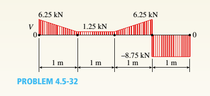
Chapter 4, Problem 4.5.32P
The shear-force diagram for a simple beam is shown in the figure.
Determine the loading on the beam and draw the bending-moment diagram, assuming that no couples act as loads on the beam.
Expert Solution & Answer

Trending nowThis is a popular solution!

Students have asked these similar questions
Please show all work step by step
Copyright 2013 Pearson Education, publishing as Prentice Hall
2. Determine the force that the jaws J of the metal cutters exert on the smooth cable C if 100-N
forces are applied to the handles. The jaws are pinned at E and A, and D and B. There is also
a pin at F.
E
400 mm
15°
D
B
30 mm² 80 mm/
20 mm
15°
$15°
20 mm
400 mm
15°
100 N
100 N
15°
Draw for it make a match which direction
Chapter 4 Solutions
Mechanics of Materials (MindTap Course List)
Ch. 4 - Calculate the shear force V and bending moment...Ch. 4 - Determine the shear force V and bending moment M...Ch. 4 - Determine the shear force V and bending moment M...Ch. 4 - Calculate the shear force V and bending moment M...Ch. 4 - Consider the beam with an overhang shown in the...Ch. 4 - The beam ABC shown in the figure is simply...Ch. 4 - The beam ABCD shown in the figure has overhangs at...Ch. 4 - At a full d raw, an archer applies a pull of 130 N...Ch. 4 - A curved bar ABC is subjected to loads in the form...Ch. 4 - Under cruising conditions, the distributed load...
Ch. 4 - A beam ABCD with a vertical arm CE is supported as...Ch. 4 - A simply supported beam AB supports a trapezoid...Ch. 4 - Beam ABCD represents a reinforced-concrete...Ch. 4 - Find shear (V) and moment (M) at x = 3L/4 for the...Ch. 4 - Find expressions for shear force V and moment M at...Ch. 4 - Find expressions for shear force V and moment Mat...Ch. 4 - Find expressions for shear force V and moment Mat...Ch. 4 - Find expressions for shear force V and moment M at...Ch. 4 - Find expressions for shear force V and moment M at...Ch. 4 - Find expressions for shear force V and moment M at...Ch. 4 - A cable with force P is attached to a frame at A...Ch. 4 - Find expressions for shear force V and moment M at...Ch. 4 - A cable with force P is attached to a frame at D...Ch. 4 - Frame ABCD carries two concentrated loads (2P at T...Ch. 4 - Frame ABC has a moment release just left of joint...Ch. 4 - The simply supported beam ABCD is loaded by a...Ch. 4 - The centrifuge shown in the figure rotates in a...Ch. 4 - Draw the shear-Force and bending-moment diagrams...Ch. 4 - A simple beam AB is subjected to a counter...Ch. 4 - Draw the shear-force and bending-moment diagrams...Ch. 4 - The cantilever beam AB shown in the figure is...Ch. 4 - Cantilever beam AB carries an upward uniform load...Ch. 4 - The simple beam AB shown in the figure is...Ch. 4 - A simple beam AB subjected to couples M1and 3M2...Ch. 4 - A simply supported beam ABC is loaded by a...Ch. 4 - A simply supported beam ABC is loaded at the end...Ch. 4 - A beam ABC is simply supported at A and B and has...Ch. 4 - Beam ABCD is simply supported at B and C and has...Ch. 4 - Draw the shear-force and bending-moment diagrams...Ch. 4 - The simple beam AB supports a triangular load of...Ch. 4 - The beam AB shown in the figure supports a uniform...Ch. 4 - A cantilever beam AB supports a couple and a...Ch. 4 - The cantilever beam A B shown in the figure is...Ch. 4 - Beam ABC has simple supports at .A and B. an...Ch. 4 - Beam ABC with an overhang at one end supports a...Ch. 4 - Consider the two beams shown in the figures. Which...Ch. 4 - The three beams in the figure have the same...Ch. 4 - The beam ABC shown in the figure is simply...Ch. 4 - A simple beam AB is loaded by two segments of...Ch. 4 - Two beams (see figure) are loaded the same and...Ch. 4 - The beam A BCD shown in the figure has overhangs...Ch. 4 - A beam ABCD with a vertical arm CE is supported as...Ch. 4 - Beams ABC and CD are supported at A,C, and D and...Ch. 4 - The simple beam ACE shown in the figure is...Ch. 4 - A beam with simple supports is subjected to a...Ch. 4 - A beam of length L is designed to support a...Ch. 4 - The compound beam ABCDE shown in the figure...Ch. 4 - Draw the shear-force and bending-moment diagrams...Ch. 4 - The shear-force diagram for a simple beam is shown...Ch. 4 - The shear-force diagram for a beam is shown in the...Ch. 4 - A compound beam (see figure) has an internal...Ch. 4 - A compound beam (see figure) has an shear release...Ch. 4 - A simple beam AB supports two connected wheel...Ch. 4 - The inclined beam represents a ladder with the...Ch. 4 - Beam ABC is supported by a tie rod CD as shown....Ch. 4 - A plane frame (see figure) consists of column AB...Ch. 4 - The plane frame shown in the figure is part of an...
Knowledge Booster


Learn more about
Need a deep-dive on the concept behind this application? Look no further. Learn more about this topic, mechanical-engineering and related others by exploring similar questions and additional content below.Similar questions
- Q.1) Block A is connected to block B by a pulley system as shown. The weights of blocks A and B are 100 lbs and 70 lbs, respectively. Assume negligible friction between the rope and all pulleys as well as between block B and the incline and neglect the mass of all pulleys and cables. Determine the angle 0 required to keep the system in equilibrium. (At least two FBDs must be drawn for full credit) B Ꮎ 000arrow_forwardpls solvearrow_forward+1. 0,63 fin r= 0.051 P The stepped rod in sketch is subjected to a tensile force that varies between 4000 and 7000 lb. The rod has a machined surface finish everywhere except the shoulder area, where a grinding operation has been performed to improve the fatigue resistance of the rod. Using a 99% probability of survival, determine the safety factor for infinite life if the rod is made of AISI 1080 steel, quenched and tempered at 800°c Use the Goodman line. Does the part fail at the fillet? Explainarrow_forward
- Solve this problem and show alll of the workarrow_forwardI need drawing solution,draw each one by one no Aiarrow_forwardQu. 17 Compute linear density values for [100] for silver (Ag). Express your answer in nm''. . Round off the answer to three significant figures. Qu. 18 Compute linear density value for [111] direction for silver (Ag). Express your answer in nm'. Round off the answer to three significant figures. Qu. 19 Compute planar density value for (100) plane for chromium (Cr). Express your answer in nm?. Round off the answer to two significant figures. Qu. 20 Compute planar density value for (110) plane for chromium (Cr). Express your answer in nm ≥ to four significant figures. show all work please in material engineeringarrow_forward
arrow_back_ios
SEE MORE QUESTIONS
arrow_forward_ios
Recommended textbooks for you
 Mechanics of Materials (MindTap Course List)Mechanical EngineeringISBN:9781337093347Author:Barry J. Goodno, James M. GerePublisher:Cengage Learning
Mechanics of Materials (MindTap Course List)
Mechanical Engineering
ISBN:9781337093347
Author:Barry J. Goodno, James M. Gere
Publisher:Cengage Learning
Understanding Shear Force and Bending Moment Diagrams; Author: The Efficient Engineer;https://www.youtube.com/watch?v=C-FEVzI8oe8;License: Standard YouTube License, CC-BY
Bending Stress; Author: moodlemech;https://www.youtube.com/watch?v=9QIqewkE6xM;License: Standard Youtube License