
Concept explainers
Videos
Solve for v(t) for t > 0 in the circuit of Figure P4.47, given that the inductor current is zero prior to t = 0. [Hint: Try a particular solution of the form
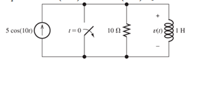
Figure P4.47
Want to see the full answer?
Check out a sample textbook solution
Chapter 4 Solutions
EP ELECTRICAL ENGR.-MODIF.MASTERINGENGR
Additional Engineering Textbook Solutions
Introduction To Programming Using Visual Basic (11th Edition)
SURVEY OF OPERATING SYSTEMS
Mechanics of Materials (10th Edition)
INTERNATIONAL EDITION---Engineering Mechanics: Statics, 14th edition (SI unit)
Database Concepts (8th Edition)
Electric Circuits. (11th Edition)


- I need handwritten solution to this, electrical engineering expert tutor s only,this is an assignment,I need 100% accuracyarrow_forward5. Determine the CT convolutions for the signals below. Sketch the signal that flips and on same plot the one that is not flipped. Do this for each overlap case. Clearly indicate all overlap cases and the integral limits. Finally, using the left squiggly bracket notation, show the output for each case versus time. (c) 4 x(t) 2 1 2(t) 4 x(t) 4 0123 et 20 x(t) (4) 4 (a) +(1) 24 T 0123 (b) T (f) 1 2-2 0123 (c) (f) 0123 (d) (1) A t 1(8) 4,121 -101 3 (e)arrow_forwardSolve by pen and paper not using chatgpt or AI Find the current io, and the voltage vo in the circuit in Figure 4. Answer: ἱο = 1.799 Α, νο = 17.99 V.arrow_forward
- "Hi Tutor, Please solve this question manually without using AI tools. AI solutions are often inaccurate in advanced electrical engineering. If you're unable to solve it manually, kindly let another qualified tutor assist me. I need reliable and accurate solutions. Thank you."arrow_forwardQ3: A conducting filamentary triangle joins points A(3, 1, 1), B(5, 4, 2), and C(1, 2, 4). The segment AB carries a current of 0.2 A in the аAB direction. There is present a magnetic field B = 0.2a, -0.1a,+ 0.3a, T. Find: (a) the force on segment BC; (b) the force on the triangular loop; (c) the torque on the loop about an origin at A; (d) the torque on the loop about an origin at C.arrow_forwardI want to find the current by using mesh analysis pleasearrow_forward
- Q2: Consider the rectangular loop shown in Figure below. Calculate the torque? Z 4 mA B, -0.6a,+0.8a, T (1, 2,0) Kamil Ans: 4.8a, mN.marrow_forwardQ4: A circular current loop of radius p and current I lies in the z = 0 plane. Find the Torque which results if the current is in the ag direction and there is a uniform field Ans: πp² Bol/√2 ay B = B₁ (ax+ay)/√2arrow_forwardQ1: A point charge for which Q = 2 x 10⁶ C is moving in the combined fields - E = 100ax 200a, +300a, V/m and B = -3ax + 2ay- az mT. If the charge velocity v = (2ax -3a, - 4a,) 105 m/s, find the unit vector showing the direction in which the charge is accelerating? Ans:.0.7ax +0.7a, -0.12a,arrow_forward
- I need help in creating a matlab code to find the currents USING MARTIXS AND INVERSE to find the currentarrow_forwardProblem 3 (a) Consider x[n] = { 0, 1, 0 ≤ n ≤N-1 otherwise _and_h[n] = { 1, 0 ≤ n ≤M-1 0, otherwise with N > M. Plot the sequence y[n] = x[n] × h[n]. Make sure to specify the amplitude values * and time indices n of y[n] where y[n] is constant. (b) Express the number L of samples of y[n] that are non-zero in terms of M and N. (c) Consider x'[n] = { 0, 1, N₁ ≤ n ≤ N₂ otherwise 1, M₁n M₂ and h'[n] = = 0, otherwise ', and assume that №2 - N₁ = N-1 and M2 - M₁ = x'[n] h'[n] is equal to a shifted version of y[n]. What is the value of the shift? - = M 1. Show that the sequence y'[n] =arrow_forwardHome Work Calculate I, and I2 in the two-port of Fig. below 20 211=602 2/30° V V₁ %12=-142 721=-j4 2 Z22=82 + V₂ 94arrow_forward
 Introductory Circuit Analysis (13th Edition)Electrical EngineeringISBN:9780133923605Author:Robert L. BoylestadPublisher:PEARSON
 Delmar's Standard Textbook Of ElectricityElectrical EngineeringISBN:9781337900348Author:Stephen L. HermanPublisher:Cengage Learning
 Programmable Logic ControllersElectrical EngineeringISBN:9780073373843Author:Frank D. PetruzellaPublisher:McGraw-Hill Education
 Fundamentals of Electric CircuitsElectrical EngineeringISBN:9780078028229Author:Charles K Alexander, Matthew SadikuPublisher:McGraw-Hill Education
 Electric Circuits. (11th Edition)Electrical EngineeringISBN:9780134746968Author:James W. Nilsson, Susan RiedelPublisher:PEARSON
 Engineering ElectromagneticsElectrical EngineeringISBN:9780078028151Author:Hayt, William H. (william Hart), Jr, BUCK, John A.Publisher:Mcgraw-hill Education,