
EP ELECTRICAL ENGR.-MODIF.MASTERINGENGR
7th Edition
ISBN: 9780134486994
Author: HAMBLEY
Publisher: PEARSON CO
expand_more
expand_more
format_list_bulleted
Concept explainers
Videos
Textbook Question
Chapter 4, Problem 4.46P
Solve for
of the form
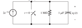
Figure P446
Expert Solution & Answer
Want to see the full answer?
Check out a sample textbook solution
Students have asked these similar questions
Apply single-phase equivalency to determine the linecurrents in the Y-D network shown in Fig. P10.13. The loadimpedances are Zab = Zbc = Zca = (25+ j5) W
10.8 In the network of Fig. P10.8, Za = Zb = Zc = (25+ j5) W.Determine the line currents.
Using D flip-flops, design a synchronous counter. The counter counts in
the sequence 1,3,5,7, 1,7,5,3,1,3,5,7,.... when its enable input x is equal
to 1; otherwise, the counter count 0.
Present state
Next state x=0
Next state x=1
Output
SO
52
S1
1
S1
54
53
3
52
53
S2
56
51
0
$5
5
54
S4
53
0
55
58
57
7
56
56
55
0
57
S10
59
1
58
58
S7
0
59
S12
S11
7
$10
$10
59
0
$11
$14
$13
5
$12
S12
$11
0
513
$15
SO
3
S14
$14
S13
0
$15
515
SO
0
Explain how to get the table step by step with drawing the state
diagram and finding the Karnaugh map.
Chapter 4 Solutions
EP ELECTRICAL ENGR.-MODIF.MASTERINGENGR
Ch. 4 - Suppose we have a capacitance C discharging...Ch. 4 - The dielectric materials used in real capacitors...Ch. 4 - The initial voltage across the capacitor shown in...Ch. 4 - A 100F capacitance is initially charged to 1000 V....Ch. 4 - At t = 0, a charged 10{ F capacitance is connected...Ch. 4 - At time t1 , a capacitance C is charged to a...Ch. 4 - Given an initially charged capacitance that begins...Ch. 4 - The initial voltage across the capacitor shown in...Ch. 4 - In physics, the half-life is often used to...Ch. 4 - We know that a 50F capacitance is charged to an...
Ch. 4 - We know that the capacitor shown in Figure P4.11...Ch. 4 - The purchasing power P of a certain unit of...Ch. 4 - Derive an expression for vC(t) in the circuit of...Ch. 4 - Suppose that at t= 0, we connect an uncharged 10 F...Ch. 4 - Suppose we have a capacitance C that is charged to...Ch. 4 - A person shuffling across a dry carpet can be...Ch. 4 - Prob. 4.17PCh. 4 - Consider the circuit shown in Figure P4.18. Prior...Ch. 4 - List the steps for dc steady-state analysis of RLC...Ch. 4 - Explain why we replace capacitances with open...Ch. 4 - Solve for the steady-state values of i1, i2, and...Ch. 4 - Consider the circuit shown in Figure P4.22. What...Ch. 4 - In the circuit of Figure P4.23, the switch is in...Ch. 4 - The circuit shown in Figure P4.24 has been set up...Ch. 4 - Solve for the steady-state values of i1 , i2, i3,...Ch. 4 - The circuit shown in Figure P4.26 is operating in...Ch. 4 - Prob. 4.27PCh. 4 - Consider the circuit of Figure P4.28 in which the...Ch. 4 - For the circuit shown in Figure P4.29, the switch...Ch. 4 - Consider the circuit of Figure P4.30 in which the...Ch. 4 - Give the expression for the time constant of a...Ch. 4 - A circuit consists of switches that open or close...Ch. 4 - The circuit shown in Figure P4.33 is operating in...Ch. 4 - Consider the circuit shown in Figure P4.34. The...Ch. 4 - Repeat Problem P4.34 given iL(0)=0A .Ch. 4 - Real inductors have series resistance associated...Ch. 4 - Determine expressions for and sketch is(t) to...Ch. 4 - For the circuit shown in Figure P4.38,, find an...Ch. 4 - The circuit shown in Figure P4.39 is operating in...Ch. 4 - Consider the circuit shown in Figure P4.40. A...Ch. 4 - Due to components not shown in the figure, the...Ch. 4 - The switch shown in Figure P4.42 has been closed...Ch. 4 - Determine expressions for and sketch vR(t) to...Ch. 4 - What are the steps in solving a circuit having a...Ch. 4 - Prob. 4.45PCh. 4 - Solve for vC(t) for t > 0 in the circuit of Figure...Ch. 4 - Solve for v(t) for t > 0 in the circuit of Figure...Ch. 4 - Prob. 4.48PCh. 4 - Consider the circuit shown inFigure P4.49. The...Ch. 4 - Consider the circuit shown in Figure P4.50. The...Ch. 4 - The voltage source shown in Figure P4.51 is called...Ch. 4 - Determine the form of the particular solution for...Ch. 4 - Determine the form of the particular solution for...Ch. 4 - Prob. 4.54PCh. 4 - Prob. 4.55PCh. 4 - How can first-or second-order circuits be...Ch. 4 - Prob. 4.57PCh. 4 - Prob. 4.58PCh. 4 - Prob. 4.59PCh. 4 - Sketch a step response for a second-order system...Ch. 4 - A dc source is connected to a series RLC circuit...Ch. 4 - Repeat Problem P4.61 for R = 40 .Ch. 4 - Repeat Problem P4.61 for R = 20 .Ch. 4 - Prob. 4.64PCh. 4 - Repeat Problem P4.64 for R=50 .Ch. 4 - Repeat Problem P4.64 for R=500 .Ch. 4 - Solve for i(t) for t > 0 in the circuit of Figure...Ch. 4 - Prob. 4.68PCh. 4 - Prob. 4.69PCh. 4 - Prob. 4.70PCh. 4 - Use MATLAB to derive an expression for vc(t)in the...Ch. 4 - Prob. 4.72PCh. 4 - Consider the circuit shown in FigureP4.50 in which...Ch. 4 - Prob. 4.74PCh. 4 - Prob. 4.75PCh. 4 - Use MATLAB to solve for the mesh currents in the...Ch. 4 - The switch m the circuit shown in Figure T4.1 is...Ch. 4 - Prob. 4.2PTCh. 4 - Consider the circuit shown in Figure T4.3. Figure...Ch. 4 - Consider the circuit shown in Figure T4.4 in which...Ch. 4 - Write the MATLAB commands to obtain the solution...
Knowledge Booster


Learn more about
Need a deep-dive on the concept behind this application? Look no further. Learn more about this topic, electrical-engineering and related others by exploring similar questions and additional content below.Similar questions
- For the oscillator resonance circuit shown in Fig. (5), derive the oscillation frequency Feedback and open-loop gains. L₁ 5 mH (a) ell +10 V R₁ ww R3 S C2 HH 1 με 1000 pF 100 pF R₂ 1 με RA H (b) +9 V R4 CA 470 pF C₁ R3 HH 1 με R₁ ww L₁ 000 1.5 mH R₂ ww Hi 1 μF L2 m 10 mHarrow_forwardExpert handwritten solution onlyarrow_forwardB. For the oscillator circuit shown in frequency, feedback and open-loop gains. +10 V name the circuit, derive and find the oscillation P.Av +9 V -000 4₁ 5 mH w R₁ C₂ HH 1 με w 100 pF R₂ T R CA www. 470 pF w ww www 1000 pF HH 1μF C₁ HH 1μF Ra ww HI 4₁ 000 1.5 mH H 4 AF 000 10 mHarrow_forward
- R₁ W +10 V R3 +9 V C₂ R₁ CA C₁ 470 pF HH 1000 pF HH 1 με C4 1 μF 1 uF C₁ R₂ R4 100 pF Find Open-loop Jain L₁ 5 mH (a) Av=S,B={" H R₁₂ ✓ ww (b) R₁ L₁ 000 1.5 mH R₂ H 1 uF 12 10 mHarrow_forwardA) Calculate the efficiency of the test transformer at the resistive loads (X-25%, 50%, 75%, 100%, 125% full load). B) From part (A) draw the plot (efficiency Vs power output) of the transformer. C) Discuss the plot of part (B).arrow_forwarda- Determine fH; and Ho b- Find fg and fr. c- Sketch the frequency response for the high-frequency region using a Bode plot and determine the cutoff frequency. Ans: 277.89 KHz; 2.73 MHz; 895.56 KHz; 107.47 MHz. 14V Cw=5pF Cwo-8pF Coc-12 pF 5.6kQ Ch. 40. pF C-8pF 68kQ 0.47µF Vo 0.82 kQ V₁ B=120 0.47µF www 3.3kQ 10kQ 1.2kQ =20µF Narrow_forward
- Using D flip-flops, design a synchronous counter. The counter counts in the sequence 1,3,5,7, 1,7,5,3,1,3,5,7,.... when its enable input x is equal to 1; otherwise, the counter. This counter is for individual settings only need the state diagram and need the state table to use 16 states from So to S15.arrow_forward: A sequential network has one input (X) and two outputs (Z1 and Z2). An output Z1 Z2 = 10 occurs every time the input sequence 1011 is completed. An output Z1 Z2 = 01 occurs every time the input sequence 0101 is completed. Otherwise Z1 Z2 = 0 Find Moore state diagram with minimum number of states: a) When overlap is allowed. b) When overlap is not allowed. I need a step by step printable solution that uses sequences on the same drawing.arrow_forward1. Consider a negative unity-feedback control system whose plant transfer function is type- 1. Suppose you want to build a lead compensator so that -3 ± 5j are dominant poles. You observed that the angle deficiency at the desired dominant pole is 50°. Compute a 's+b' and b of the lead compensator (s+ 2) so that the error constant Ky is maximized. In other words, design the lead compensator in a way so that the steady-state error for ramp input is minimumarrow_forward
arrow_back_ios
SEE MORE QUESTIONS
arrow_forward_ios
Recommended textbooks for you
 Introductory Circuit Analysis (13th Edition)Electrical EngineeringISBN:9780133923605Author:Robert L. BoylestadPublisher:PEARSON
 Delmar's Standard Textbook Of ElectricityElectrical EngineeringISBN:9781337900348Author:Stephen L. HermanPublisher:Cengage Learning
 Programmable Logic ControllersElectrical EngineeringISBN:9780073373843Author:Frank D. PetruzellaPublisher:McGraw-Hill Education
 Fundamentals of Electric CircuitsElectrical EngineeringISBN:9780078028229Author:Charles K Alexander, Matthew SadikuPublisher:McGraw-Hill Education
 Electric Circuits. (11th Edition)Electrical EngineeringISBN:9780134746968Author:James W. Nilsson, Susan RiedelPublisher:PEARSON
 Engineering ElectromagneticsElectrical EngineeringISBN:9780078028151Author:Hayt, William H. (william Hart), Jr, BUCK, John A.Publisher:Mcgraw-hill Education,
Introductory Circuit Analysis (13th Edition)
Electrical Engineering
ISBN:9780133923605
Author:Robert L. Boylestad
Publisher:PEARSON
Delmar's Standard Textbook Of Electricity
Electrical Engineering
ISBN:9781337900348
Author:Stephen L. Herman
Publisher:Cengage Learning
Programmable Logic Controllers
Electrical Engineering
ISBN:9780073373843
Author:Frank D. Petruzella
Publisher:McGraw-Hill Education
Fundamentals of Electric Circuits
Electrical Engineering
ISBN:9780078028229
Author:Charles K Alexander, Matthew Sadiku
Publisher:McGraw-Hill Education
Electric Circuits. (11th Edition)
Electrical Engineering
ISBN:9780134746968
Author:James W. Nilsson, Susan Riedel
Publisher:PEARSON
Engineering Electromagnetics
Electrical Engineering
ISBN:9780078028151
Author:Hayt, William H. (william Hart), Jr, BUCK, John A.
Publisher:Mcgraw-hill Education,
Capacitors Explained - The basics how capacitors work working principle; Author: The Engineering Mindset;https://www.youtube.com/watch?v=X4EUwTwZ110;License: Standard YouTube License, CC-BY