
Interpretation:
The applied stress needed to cause the slip to begin in the
Concept Introduction:
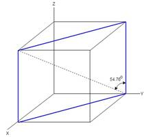
The angle between the normal to the slip plane and the applied force can be calculated as follows:
Here,
Answer to Problem 4.43P
The applied stress that causes the slip on the plane
The applied stress that causes the slip on the plane
The applied stress that causes the slip on the plane
Explanation of Solution
The angle between the normal to the slip plane and the applied force can be calculated as follows:
Here,
Substitute
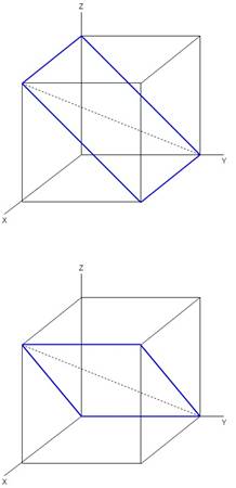
The angle between the slip direction and the applied force slip plane
Here,
Substitute
Calculate the angel between the slip direction and the applied force slip plane
Here,
Substitute
The angle between the slip direction and the applied force slip plane
Here,
Substitute
The cubic crystal system that represents the orientation of different planes is as follows:
The applied stress produces resolved shear stress,
Apply Schmidt's law and calculate the applied stress that causes the slip on the plane
Substitute
Therefore, the applied stress that causes the slip on the plane
Apply Schmidt's law and calculate the applied stress that causes the slip on the plane
Substitute
Therefore, the applied stress that causes the slip on the plane
The applied stress that causes the slip on the plane
The applied stress that causes the slip on the plane
The applied stress that causes the slip on the plane
Want to see more full solutions like this?
Chapter 4 Solutions
Essentials Of Materials Science And Engineering, Si Edition

- Q11arrow_forwardMethyl alcohol at 25°C (ρ = 789 kg/m³, μ = 5.6 × 10⁻⁴ kg/m∙s) flows through the system below at a rate of 0.015 m³/s. Fluid enters the suction line from reservoir 1 (left) through a sharp-edged inlet. The suction line is 10 cm commercial steel pipe, 15 m long. Flow passes through a pump with efficiency of 76%. Flow is discharged from the pump into a 5 cm line, through a fully open globe valve and a standard smooth threaded 90° elbow before reaching a long, straight discharge line. The discharge line is 5 cm commercial steel pipe, 200 m long. Flow then passes a second standard smooth threaded 90° elbow before discharging through a sharp-edged exit to reservoir 2 (right). Pipe lengths between the pump and valve, and connecting the second elbow to the exit are negligibly short compared to the suction and discharge lines. Volumes of reservoirs 1 and 2 are large compared to volumes extracted or supplied by the suction and discharge lines. Calculate the power that must be supplied to the…arrow_forwardQ15arrow_forward
- 2) The transistor parameters of the NMOS device in the common-gate amplifier in Figure 2 are VTN = 0.4V, K'n = 100 μA / V², and λ=0. (50 points) a) Find RD such that VDSQ = VDs (sat) + 0.25V. b) Determine the transistor W/L ratio such that the small-signal voltage gain is Av=6. c) What is the value of VGSQ? Сс 2 mA Rp T V=-1.8 V V+= 1.8 V Figure 2arrow_forwardAnswer the question fully and accurately by providing the required files(Java Code, Two output files and written answers to questions 1-3 in a word document)meaning question 1 to 3 also provide correct answers for those questions.(note: this quetion is not graded).arrow_forwardcan you help me figure out the calculations so that i can input into autocad? Not apart of a graded assinment. Just a problem in class that i missed.arrow_forward
- Calculate the percent voltage regulation for a three-phase wye-connected 2500 kVA 6600-V turboalternator operating at full-load Unity power factor The per phase synchronous reactance and the armature resistance are 10.4 2 and 0.071 ≤2, respectively?arrow_forwardConsider a glass window (Hight = 1.2 m, Width = 2 m). The room thatfaces the window are maintained at 25 o C. The average temperature ofthe inner surface of the window is 5 o C. Calculate the total heat transferrate from through the window a) IdenCfy what type(s) of convecCon is important (circle one). • external forced (Chapter 7)• internal forced (Chapter 8)• natural convecCon (Chapter 9)• boiling and condensaCon (Chapter 10)b) IdenCfy the necessary equaCon(s) needed to solve the problem. c) IdenCfy important fluid properCes you need to solve the problem. d) Calculate the total heat transferred.arrow_forwardWater is condensing on a square plate (0.5 m x 0.5 m) placed verCcally. If the desired rate ofcondensaCon is 0.016 kJ/s, determine the necessary surface temperature of the plate at atmosphericpressure. Assume the film temperature of 90 o C for evaluaCon of fluid properCes of water and thesurface temperature of 80 o C for the evaluaCon of modified latent heat of vaporizaConarrow_forward
 MATLAB: An Introduction with ApplicationsEngineeringISBN:9781119256830Author:Amos GilatPublisher:John Wiley & Sons Inc
 Essentials Of Materials Science And EngineeringEngineeringISBN:9781337385497Author:WRIGHT, Wendelin J.Publisher:Cengage,
 Industrial Motor ControlEngineeringISBN:9781133691808Author:Stephen HermanPublisher:Cengage Learning
 Basics Of Engineering EconomyEngineeringISBN:9780073376356Author:Leland Blank, Anthony TarquinPublisher:MCGRAW-HILL HIGHER EDUCATION
 Structural Steel Design (6th Edition)EngineeringISBN:9780134589657Author:Jack C. McCormac, Stephen F. CsernakPublisher:PEARSON
 Fundamentals of Materials Science and Engineering...EngineeringISBN:9781119175483Author:William D. Callister Jr., David G. RethwischPublisher:WILEY