
Electrical Engineering: Principles & Applications, Student Value Edition Plus Mastering Engineering with Pearson eText -- Access Card Package (7th Edition)
7th Edition
ISBN: 9780134702193
Author: Allan R. Hambley
Publisher: PEARSON
expand_more
expand_more
format_list_bulleted
Videos
Textbook Question
Chapter 4, Problem 4.38P
For the circuit shown in Figure P4.38,, find an expression for the current
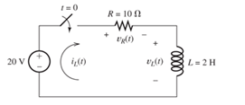
Figure P4.38
Expert Solution & Answer
Want to see the full answer?
Check out a sample textbook solution
Students have asked these similar questions
Open plc - ladder logic To control traffic, we have red lights to stop cars and green lights to initiate entry/exit.
If a car is in the lane, then the red lights turn ON. If no cars are in the lane, then the
green lights turn ON. Upon turning ON the main switch button, the main switch indicator
should turn ON and the system should start with green lights ON and red lights OFF?
3-4)
3.4-2 Signals g₁(t) = 104П(104) and g2(t) = 8(t) are applied at the inputs of the ideal low-pass
filters H₁(f)=(f/20,000) and H2(f) = П(f/10,000) (Fig. P3.4-2). The outputs y₁ (t) and
y2(t) of these filters are multiplied to obtain the signal y(t) = y1 (1)y2(t).
(a) Sketch G1(f) and G2(f).
(b) Sketch H₁(f) and H₂(f).
(c) Sketch Y₁ (f) and Y2(f).
(d) Find the bandwidths of y₁ (t), y2(t), and y(t).
8₁ (1)
H₁(f)
y, (t)
y(t) = y₁ (1) y2 (1)
82(1)
½⁄2 (1)
H₂(f)
solve the differential equation y'' -2y'-3y=x³e^5x cos(3x)
Don't use AI,I need it handwritten
Chapter 4 Solutions
Electrical Engineering: Principles & Applications, Student Value Edition Plus Mastering Engineering with Pearson eText -- Access Card Package (7th Edition)
Ch. 4 - Suppose we have a capacitance C discharging...Ch. 4 - The dielectric materials used in real capacitors...Ch. 4 - The initial voltage across the capacitor shown in...Ch. 4 - A 100F capacitance is initially charged to 1000 V....Ch. 4 - At t = 0, a charged 10{ F capacitance is connected...Ch. 4 - At time t1 , a capacitance C is charged to a...Ch. 4 - Given an initially charged capacitance that begins...Ch. 4 - The initial voltage across the capacitor shown in...Ch. 4 - In physics, the half-life is often used to...Ch. 4 - We know that a 50F capacitance is charged to an...
Ch. 4 - We know that the capacitor shown in Figure P4.11...Ch. 4 - The purchasing power P of a certain unit of...Ch. 4 - Derive an expression for vC(t) in the circuit of...Ch. 4 - Suppose that at t= 0, we connect an uncharged 10 F...Ch. 4 - Suppose we have a capacitance C that is charged to...Ch. 4 - A person shuffling across a dry carpet can be...Ch. 4 - Prob. 4.17PCh. 4 - Consider the circuit shown in Figure P4.18. Prior...Ch. 4 - List the steps for dc steady-state analysis of RLC...Ch. 4 - Explain why we replace capacitances with open...Ch. 4 - Solve for the steady-state values of i1, i2, and...Ch. 4 - Consider the circuit shown in Figure P4.22. What...Ch. 4 - In the circuit of Figure P4.23, the switch is in...Ch. 4 - The circuit shown in Figure P4.24 has been set up...Ch. 4 - Solve for the steady-state values of i1 , i2, i3,...Ch. 4 - The circuit shown in Figure P4.26 is operating in...Ch. 4 - Prob. 4.27PCh. 4 - Consider the circuit of Figure P4.28 in which the...Ch. 4 - For the circuit shown in Figure P4.29, the switch...Ch. 4 - Consider the circuit of Figure P4.30 in which the...Ch. 4 - Give the expression for the time constant of a...Ch. 4 - A circuit consists of switches that open or close...Ch. 4 - The circuit shown in Figure P4.33 is operating in...Ch. 4 - Consider the circuit shown in Figure P4.34. The...Ch. 4 - Repeat Problem P4.34 given iL(0)=0A .Ch. 4 - Real inductors have series resistance associated...Ch. 4 - Determine expressions for and sketch is(t) to...Ch. 4 - For the circuit shown in Figure P4.38,, find an...Ch. 4 - The circuit shown in Figure P4.39 is operating in...Ch. 4 - Consider the circuit shown in Figure P4.40. A...Ch. 4 - Due to components not shown in the figure, the...Ch. 4 - The switch shown in Figure P4.42 has been closed...Ch. 4 - Determine expressions for and sketch vR(t) to...Ch. 4 - What are the steps in solving a circuit having a...Ch. 4 - Prob. 4.45PCh. 4 - Solve for vC(t) for t > 0 in the circuit of Figure...Ch. 4 - Solve for v(t) for t > 0 in the circuit of Figure...Ch. 4 - Prob. 4.48PCh. 4 - Consider the circuit shown inFigure P4.49. The...Ch. 4 - Consider the circuit shown in Figure P4.50. The...Ch. 4 - The voltage source shown in Figure P4.51 is called...Ch. 4 - Determine the form of the particular solution for...Ch. 4 - Determine the form of the particular solution for...Ch. 4 - Prob. 4.54PCh. 4 - Prob. 4.55PCh. 4 - How can first-or second-order circuits be...Ch. 4 - Prob. 4.57PCh. 4 - Prob. 4.58PCh. 4 - Prob. 4.59PCh. 4 - Sketch a step response for a second-order system...Ch. 4 - A dc source is connected to a series RLC circuit...Ch. 4 - Repeat Problem P4.61 for R = 40 .Ch. 4 - Repeat Problem P4.61 for R = 20 .Ch. 4 - Prob. 4.64PCh. 4 - Repeat Problem P4.64 for R=50 .Ch. 4 - Repeat Problem P4.64 for R=500 .Ch. 4 - Solve for i(t) for t > 0 in the circuit of Figure...Ch. 4 - Prob. 4.68PCh. 4 - Prob. 4.69PCh. 4 - Prob. 4.70PCh. 4 - Use MATLAB to derive an expression for vc(t)in the...Ch. 4 - Prob. 4.72PCh. 4 - Consider the circuit shown in FigureP4.50 in which...Ch. 4 - Prob. 4.74PCh. 4 - Prob. 4.75PCh. 4 - Use MATLAB to solve for the mesh currents in the...Ch. 4 - The switch m the circuit shown in Figure T4.1 is...Ch. 4 - Prob. 4.2PTCh. 4 - Consider the circuit shown in Figure T4.3. Figure...Ch. 4 - Consider the circuit shown in Figure T4.4 in which...Ch. 4 - Write the MATLAB commands to obtain the solution...
Knowledge Booster


Learn more about
Need a deep-dive on the concept behind this application? Look no further. Learn more about this topic, electrical-engineering and related others by exploring similar questions and additional content below.Similar questions
- 3-3) Similar to Lathi & Ding prob. 3.3-7. The signals in the figure below are modulated signals with carrier cos(5t). Find the Fourier transforms of these signals using the appropriate properties of the Fourier transform and text Table 3.1. The sketch the magnitude and phase spectra for figure parts (a) and (b). Hint: these functions can be expressed in the form g(t) cos(2лfot) (a) 1 1 2π www. σπ (b) (c) όπarrow_forward3-1) Similar to Lathi & Ding prob. 3.1-1. Use direct integration to find the Fourier transforms of the signals shown below. a) g₁(t) = II(t − 2) + 2 exp (−3|t|) b) g(t) = d(t+2)+3e¯u (t − 2)arrow_forward3-2) Lathi & Ding prob. 3.1-5. From the definition in eq. 3.1b, find the inverse Fourier transforms of the spectra in the figure below. G(f) COS лf 10 (a) G(f) 1 -B B (b)arrow_forward
- Construct a battery pack to deliver 360V and 450-mile range for a vehicle that consumes 200 Wh/mile, from prismatic cells with 25Ah and 3.6 V. Physical dimensions of the cell are 0.5 cm thickness, 20 cm width and 40 cm length. a) Report configuration of the battery pack. 10-points b) Resistance of each cell is 0.05 Ohm, calculate the total internal resistance of the battery pack. 10-points c) Calculate the voltage drop during discharge when the battery is discharged at 100A. 10-points d) Calculate the amount of anode and cathode to build a prismatic cell with 25Ah capacity. Assume the cell chemistry as: Si anode and [Li(Ni1/3Co1/3Mn1/3)O2] cathode. Atomic weight of elements: Li=7, Si = 28, Ni=58, Co=59, Mn=55, O=16, 10-points e) Calculate the theoretical specific energy (Wh/kg) and practical energy density (Wh/liter) of the battery pack. 10-points f) Calculate the thickness on anode and cathode coating assuming each electrode has 30%…arrow_forwardI need help with this problem and an explanation of the solution for the image described below. (Introduction to Signals and Systems)arrow_forwardDesign a battery pack for an electric bike that consumes in average 10Wh/mile and drive 30 miles per charge. The battery state of charge window is 80%. Design the battery by using new commercial cylindrical cells with 20mm diameter and 80mm height. The battery is constructed based on graphite anode C6 and cathode Li(Ni0.8Co0.15Al0,05)O2 that provides 3.75V at the cell level and 10Ah capacity. Density of anode is 2.2 g/cm3 and density of cathode is 4.5 g/cm3. Report on the battery pack configuration if the required battery pack voltage is 75 volts. If the thickness of anode and cathode is limited to 130 microns (130 x 10-4 cm) calculate the total electrode surface area in each cell. Assume the porosity of electrodes are 30%. Calculate the weight of active materials (anode and cathode) in grams and the total current collector’s and electrolyte membrane areas in (cm2).arrow_forward
arrow_back_ios
SEE MORE QUESTIONS
arrow_forward_ios
Recommended textbooks for you
 Introductory Circuit Analysis (13th Edition)Electrical EngineeringISBN:9780133923605Author:Robert L. BoylestadPublisher:PEARSON
 Delmar's Standard Textbook Of ElectricityElectrical EngineeringISBN:9781337900348Author:Stephen L. HermanPublisher:Cengage Learning
 Programmable Logic ControllersElectrical EngineeringISBN:9780073373843Author:Frank D. PetruzellaPublisher:McGraw-Hill Education
 Fundamentals of Electric CircuitsElectrical EngineeringISBN:9780078028229Author:Charles K Alexander, Matthew SadikuPublisher:McGraw-Hill Education
 Electric Circuits. (11th Edition)Electrical EngineeringISBN:9780134746968Author:James W. Nilsson, Susan RiedelPublisher:PEARSON
 Engineering ElectromagneticsElectrical EngineeringISBN:9780078028151Author:Hayt, William H. (william Hart), Jr, BUCK, John A.Publisher:Mcgraw-hill Education,
Introductory Circuit Analysis (13th Edition)
Electrical Engineering
ISBN:9780133923605
Author:Robert L. Boylestad
Publisher:PEARSON
Delmar's Standard Textbook Of Electricity
Electrical Engineering
ISBN:9781337900348
Author:Stephen L. Herman
Publisher:Cengage Learning
Programmable Logic Controllers
Electrical Engineering
ISBN:9780073373843
Author:Frank D. Petruzella
Publisher:McGraw-Hill Education
Fundamentals of Electric Circuits
Electrical Engineering
ISBN:9780078028229
Author:Charles K Alexander, Matthew Sadiku
Publisher:McGraw-Hill Education
Electric Circuits. (11th Edition)
Electrical Engineering
ISBN:9780134746968
Author:James W. Nilsson, Susan Riedel
Publisher:PEARSON
Engineering Electromagnetics
Electrical Engineering
ISBN:9780078028151
Author:Hayt, William H. (william Hart), Jr, BUCK, John A.
Publisher:Mcgraw-hill Education,
ECE320 Lecture1-3c: Steady-State Error, System Type; Author: Rose-Hulman Online;https://www.youtube.com/watch?v=hG7dq-51AAg;License: Standard Youtube License