
Electrical Engineering: Principles & Applications, Student Value Edition Plus Mastering Engineering with Pearson eText -- Access Card Package (7th Edition)
7th Edition
ISBN: 9780134702193
Author: Allan R. Hambley
Publisher: PEARSON
expand_more
expand_more
format_list_bulleted
Concept explainers
Videos
Textbook Question
Chapter 4, Problem 4.33P
The circuit shown in Figure P4.33 is operating in steady state with the switch closed prior to t = 0. Find i(t) for t < 0 and for
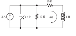
Figure P4.33
Expert Solution & Answer

Learn your wayIncludes step-by-step video

schedule05:45
Students have asked these similar questions
5. Consider the ac equivalent circuit of an
amplifier, where RE = 1 KS2, gm = 0.05 S, and
Υπ= 2Κ Ω.
(a) Redraw the ac equivalent circuit using the
hybrid-pi small signal model for BJTS.
Include ro in the model.
R₁
ww
Vi
RB
ww
+
RL
Vo
RE
(b) Find the terminal resistance RIB using the circuit obtained in (a). Ignore ro. Show your
work. (Don't use formula for RiB.)
4. Consider the circuit. Use the symbol ||
to indicate the parallel of resistors in the
following questions.
(a) Express the input resistance Rin in terms of
the terminal resistance and other necessary
resistor values. (In other words, RiB, Ric, and
RIE are given.)
C₁
R₁
R₂
+Vcc
Rc
C3
R3
C2
ی
RE
-VEE
(b) Express the output resistance Rout in terms of the terminal resistance and other necessary
resistor values. (In other words, RiB, Ric and RiE are given.)
(c) Express the voltage gain A₁ = ∞ in terms of terminal voltage gain Avt, the terminal
Vi
resistance, and other necessary resistor values. (Avt, RiB, Ric and R₁E are given.)
+51
2. ẞ 100, VBE(on)= 0.7 V, and VCE(sat) = 0.2 V for the BJT. We want
to find the Q-point through the following steps. Show your work.
a) Find the bias voltage VTH Using Thevenin's equivalent circuit.
R1|| R2
www
+5 V
R₁ = 20 k
IB
VTH
Answer: VTH =
V
b) Find the base current voltage IB.
www.
Answer: IB =
μA (note the unit.)
c) Find the collector voltage Vc (with reference to the ground).
RC= 2.3 k
B
E
R₂ = 30 k
-5 V
www
R₁ =
5 ΚΩ
ww
AHI›
RE=
5 ΚΩ
Chapter 4 Solutions
Electrical Engineering: Principles & Applications, Student Value Edition Plus Mastering Engineering with Pearson eText -- Access Card Package (7th Edition)
Ch. 4 - Suppose we have a capacitance C discharging...Ch. 4 - The dielectric materials used in real capacitors...Ch. 4 - The initial voltage across the capacitor shown in...Ch. 4 - A 100F capacitance is initially charged to 1000 V....Ch. 4 - At t = 0, a charged 10{ F capacitance is connected...Ch. 4 - At time t1 , a capacitance C is charged to a...Ch. 4 - Given an initially charged capacitance that begins...Ch. 4 - The initial voltage across the capacitor shown in...Ch. 4 - In physics, the half-life is often used to...Ch. 4 - We know that a 50F capacitance is charged to an...
Ch. 4 - We know that the capacitor shown in Figure P4.11...Ch. 4 - The purchasing power P of a certain unit of...Ch. 4 - Derive an expression for vC(t) in the circuit of...Ch. 4 - Suppose that at t= 0, we connect an uncharged 10 F...Ch. 4 - Suppose we have a capacitance C that is charged to...Ch. 4 - A person shuffling across a dry carpet can be...Ch. 4 - Prob. 4.17PCh. 4 - Consider the circuit shown in Figure P4.18. Prior...Ch. 4 - List the steps for dc steady-state analysis of RLC...Ch. 4 - Explain why we replace capacitances with open...Ch. 4 - Solve for the steady-state values of i1, i2, and...Ch. 4 - Consider the circuit shown in Figure P4.22. What...Ch. 4 - In the circuit of Figure P4.23, the switch is in...Ch. 4 - The circuit shown in Figure P4.24 has been set up...Ch. 4 - Solve for the steady-state values of i1 , i2, i3,...Ch. 4 - The circuit shown in Figure P4.26 is operating in...Ch. 4 - Prob. 4.27PCh. 4 - Consider the circuit of Figure P4.28 in which the...Ch. 4 - For the circuit shown in Figure P4.29, the switch...Ch. 4 - Consider the circuit of Figure P4.30 in which the...Ch. 4 - Give the expression for the time constant of a...Ch. 4 - A circuit consists of switches that open or close...Ch. 4 - The circuit shown in Figure P4.33 is operating in...Ch. 4 - Consider the circuit shown in Figure P4.34. The...Ch. 4 - Repeat Problem P4.34 given iL(0)=0A .Ch. 4 - Real inductors have series resistance associated...Ch. 4 - Determine expressions for and sketch is(t) to...Ch. 4 - For the circuit shown in Figure P4.38,, find an...Ch. 4 - The circuit shown in Figure P4.39 is operating in...Ch. 4 - Consider the circuit shown in Figure P4.40. A...Ch. 4 - Due to components not shown in the figure, the...Ch. 4 - The switch shown in Figure P4.42 has been closed...Ch. 4 - Determine expressions for and sketch vR(t) to...Ch. 4 - What are the steps in solving a circuit having a...Ch. 4 - Prob. 4.45PCh. 4 - Solve for vC(t) for t > 0 in the circuit of Figure...Ch. 4 - Solve for v(t) for t > 0 in the circuit of Figure...Ch. 4 - Prob. 4.48PCh. 4 - Consider the circuit shown inFigure P4.49. The...Ch. 4 - Consider the circuit shown in Figure P4.50. The...Ch. 4 - The voltage source shown in Figure P4.51 is called...Ch. 4 - Determine the form of the particular solution for...Ch. 4 - Determine the form of the particular solution for...Ch. 4 - Prob. 4.54PCh. 4 - Prob. 4.55PCh. 4 - How can first-or second-order circuits be...Ch. 4 - Prob. 4.57PCh. 4 - Prob. 4.58PCh. 4 - Prob. 4.59PCh. 4 - Sketch a step response for a second-order system...Ch. 4 - A dc source is connected to a series RLC circuit...Ch. 4 - Repeat Problem P4.61 for R = 40 .Ch. 4 - Repeat Problem P4.61 for R = 20 .Ch. 4 - Prob. 4.64PCh. 4 - Repeat Problem P4.64 for R=50 .Ch. 4 - Repeat Problem P4.64 for R=500 .Ch. 4 - Solve for i(t) for t > 0 in the circuit of Figure...Ch. 4 - Prob. 4.68PCh. 4 - Prob. 4.69PCh. 4 - Prob. 4.70PCh. 4 - Use MATLAB to derive an expression for vc(t)in the...Ch. 4 - Prob. 4.72PCh. 4 - Consider the circuit shown in FigureP4.50 in which...Ch. 4 - Prob. 4.74PCh. 4 - Prob. 4.75PCh. 4 - Use MATLAB to solve for the mesh currents in the...Ch. 4 - The switch m the circuit shown in Figure T4.1 is...Ch. 4 - Prob. 4.2PTCh. 4 - Consider the circuit shown in Figure T4.3. Figure...Ch. 4 - Consider the circuit shown in Figure T4.4 in which...Ch. 4 - Write the MATLAB commands to obtain the solution...
Additional Engineering Textbook Solutions
Find more solutions based on key concepts
The following is a multiplication problem in traditional base ten notation. Each letter represents a different ...
Computer Science: An Overview (13th Edition) (What's New in Computer Science)
If the block is held in the equilibrium position shown, determine the mass of the block at D.
INTERNATIONAL EDITION---Engineering Mechanics: Statics, 14th edition (SI unit)
Determine the maximum normal stress developed in the bar when it is subjected to a tension of P = 8kN.
Mechanics of Materials (10th Edition)
3.1 Discuss the differences between an error and a residual.
Elementary Surveying: An Introduction To Geomatics (15th Edition)
In the following exercises, write a program to carry out the task. The program should use variables for each of...
Introduction To Programming Using Visual Basic (11th Edition)
Distinguish among data definition commands, data manipulation commands, and data control commands.
Modern Database Management
Knowledge Booster


Learn more about
Need a deep-dive on the concept behind this application? Look no further. Learn more about this topic, electrical-engineering and related others by exploring similar questions and additional content below.Similar questions
- 3. Consider the circuit, in which R₁ = 10 KQ2, R2 = 5 KQ, R3 = 1 KQ, and RE = 8 KQ. The supply voltages are +Vcc = 10 V and -VEE = -5 V. Other parameters are ẞF = 100, VBE(On) = 0.7 V, and VCE(Sat) 0.2 V. Rc value will be specified later. (a) (3 points) Draw the dc equivalent circuit of the circuit. VI +Vcc Rc R2 RI R₁ RE -VEE υο R3 (b) Find the Thevenin equivalent voltage source VEQ and input resistance REQ of the DC equivalent circuit. Show your work. +Vcc Rc UC VEQ www REQ VE VEQ = REQ = ΚΩ RE VEEarrow_forwardThe solution is with a pen and paper. Really not smartarrow_forward1. Consider the following mechanical system. Obtain the differential equation model for the system. Write the transfer function of the system also. Note here, input u(t) is force and output x(t) is the displacement of the mass. x (Output) k1 k2 www u(t) m (Input force) No frictionarrow_forward
- NO AI PLEASEarrow_forward2. Consider the following mechanical system with two masses. Find the differential equation model for the system. Find the transfer functions X1(s) and U(s) Note, in the figure, x₁ and x2 are displacements and u is the force. X2(s) U(s) also. k₁ www + b₁ " x1 k2 kz www mi www m2 Đ b₂arrow_forward4. Find the transfer function H(s) = = Vo(s) V₁(s) for the following circuit. Vi R₁ ww A R₂ ww Voarrow_forward
- Answer the following questions. Take help from ChatGPT to answer these questions (if you need). But write the answers briefly using your own words with no more than two sentences and make sure you check whether ChatGPT is giving you the appropriate answers in our context. A) Write Newton’s second law of motion. B) What is a dashpot? C) What is Hooke’s law? Why there is a negative sign? D) Write the voltage and current equation for an Ideal Op-amp.arrow_forward3. Find the differential Equation model for the following electrical circuit. Write the transfer function also. Here, input u(t) is a current source and output y(t) is the current through the resistor R. u(t) (I) 州 BRarrow_forwardNO AI PLEASEarrow_forward
arrow_back_ios
SEE MORE QUESTIONS
arrow_forward_ios
Recommended textbooks for you
 Introductory Circuit Analysis (13th Edition)Electrical EngineeringISBN:9780133923605Author:Robert L. BoylestadPublisher:PEARSON
 Delmar's Standard Textbook Of ElectricityElectrical EngineeringISBN:9781337900348Author:Stephen L. HermanPublisher:Cengage Learning
 Programmable Logic ControllersElectrical EngineeringISBN:9780073373843Author:Frank D. PetruzellaPublisher:McGraw-Hill Education
 Fundamentals of Electric CircuitsElectrical EngineeringISBN:9780078028229Author:Charles K Alexander, Matthew SadikuPublisher:McGraw-Hill Education
 Electric Circuits. (11th Edition)Electrical EngineeringISBN:9780134746968Author:James W. Nilsson, Susan RiedelPublisher:PEARSON
 Engineering ElectromagneticsElectrical EngineeringISBN:9780078028151Author:Hayt, William H. (william Hart), Jr, BUCK, John A.Publisher:Mcgraw-hill Education,
Introductory Circuit Analysis (13th Edition)
Electrical Engineering
ISBN:9780133923605
Author:Robert L. Boylestad
Publisher:PEARSON
Delmar's Standard Textbook Of Electricity
Electrical Engineering
ISBN:9781337900348
Author:Stephen L. Herman
Publisher:Cengage Learning
Programmable Logic Controllers
Electrical Engineering
ISBN:9780073373843
Author:Frank D. Petruzella
Publisher:McGraw-Hill Education
Fundamentals of Electric Circuits
Electrical Engineering
ISBN:9780078028229
Author:Charles K Alexander, Matthew Sadiku
Publisher:McGraw-Hill Education
Electric Circuits. (11th Edition)
Electrical Engineering
ISBN:9780134746968
Author:James W. Nilsson, Susan Riedel
Publisher:PEARSON
Engineering Electromagnetics
Electrical Engineering
ISBN:9780078028151
Author:Hayt, William H. (william Hart), Jr, BUCK, John A.
Publisher:Mcgraw-hill Education,
Capacitors Explained - The basics how capacitors work working principle; Author: The Engineering Mindset;https://www.youtube.com/watch?v=X4EUwTwZ110;License: Standard YouTube License, CC-BY