
EBK COMPUTER SCIENCE ILLUMINATED
7th Edition
ISBN: 9781284174755
Author: Dale
Publisher: JONES+B CO
expand_more
expand_more
format_list_bulleted
Videos
Expert Solution & Answer
Chapter 4, Problem 35E
Explanation of Solution
Gates:
- A gate is a device which is used to perform the basic logical operation.
- It accepts one or more input signals and generates single output signal.
- It contains several types of gates.
- Six types of gates are most commonly used. They are:
- NOT gate
- AND gate
- OR gate
- XOR gate
- NAND gate
- NOR gate
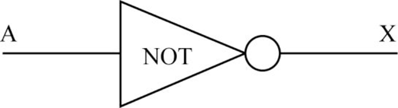
- NOT gate:
- A NOT gate accepts only one input value to generate single output value.
- When the input is 0, then the output is 1. The output of the NOT gate is the inversion of its input.
- So, it is also referred to as inverter.
- It is represented in three ways:
- In “Boolean expression”, the NOT operation is expressed using the “
- In “Boolean expression”, the NOT operation is expressed using the “
Where A is the input and X is the output.
- The “logic diagram” for NOT gate takes A as input and generates a single X as output:
- The “Truth table” for the NOT gate:
| A | |
| 0 | 1 |
| 1 | 0 |
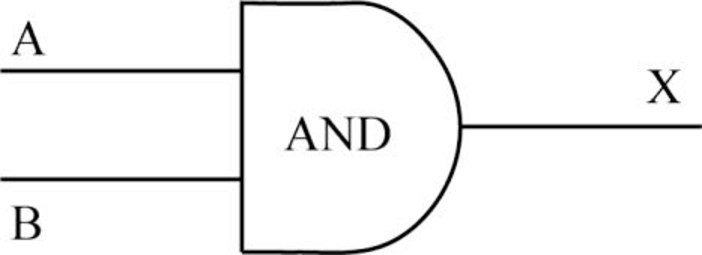
- AND gate:
- An AND gate accepts two inputs and generates a single output.
- When both the inputs are 1, then the output is 1. Otherwise, the output is 0.
- It is represented in three ways:
- In “Boolean expression”, the AND operation is expressed using the “.” dot operator or “*” asterisk operator.
Where A and B are the inputs and X is the output.
- The “logic diagram” for AND gate takes two inputs and generates a single output:
- The “Truth table” for the AND gate:
| A | B | |
| 0 | 0 | 0 |
| 0 | 1 | 0 |
| 1 | 0 | 0 |
| 1 | 1 | 1 |
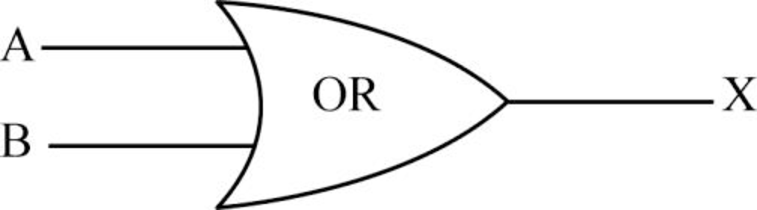
- OR gate:
- An OR gate accepts two inputs and generates a single output.
- When both the inputs are 0, then the output is 0. Otherwise, the output is 1.
- It is represented in three ways:
- In “Boolean expression”, the OR operation is expressed using the “+” plus sign.
- In “Boolean expression”, the OR operation is expressed using the “+” plus sign.
Where A and B are the inputs and X is the output.
- The “logic diagram” for OR gate takes two inputs and generates a single output:
- The “Truth table” for the OR gate:
| A | B | |
| 0 | 0 | 0 |
| 0 | 1 | 1 |
| 1 | 0 | 1 |
| 1 | 1 | 1 |
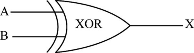
- XOR gate:
- An XOR gate accepts two inputs and produces a single output.
- When both the inputs are same, then the output is 0. Otherwise, the output is 1.
- It is represented in three ways:
- In “Boolean expression”, the XOR operation is expressed by using the “
- In “Boolean expression”, the XOR operation is expressed by using the “
Where A and B are the inputs and X is the output.
- The “logic diagram” for XOR gate takes two inputs and generates a single output:
- The “Truth table” for the XOR gate:
| A | B | X = A |
| 0 | 0 | 0 |
| 0 | 1 | 1 |
| 1 | 0 | 1 |
| 1 | 1 | 0 |
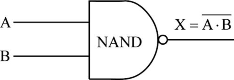
- NAND gate:
- The NAND gate accepts two inputs and produces a single output.
- It produces the opposite results of an AND gate.
- If both the inputs are 1, then the output is 0. Otherwise, the output is 1.
- It is represented in three ways:
- The “Boolean expression” for NAND gate:
- No specific symbol is used to express the NAND operation.
- The expression for NAND is the negation of an AND operation.
- The “Boolean expression” for NAND gate:
Where A and B are the inputs and X is the output.
- The “logic diagram” for NAND gate:
- It takes two inputs and generates a single output.
- The “Truth table” for the NAND gate:
| A | B | |
| 0 | 0 | 1 |
| 0 | 1 | 1 |
| 1 | 0 | 1 |
| 1 | 1 | 0 |
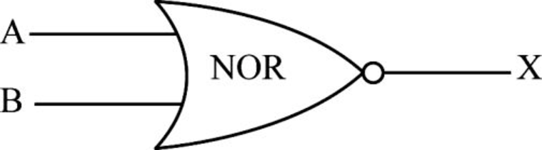
- NOR gate:
- The NOR gate accepts two inputs and produces a single output.
- It produces the opposite results of an OR gate.
- If both the inputs are 0, then only the output is 1. Otherwise, the output is 0.
- It is represented in three ways:
- In “Boolean expression”,
- No specific symbol is used to express the NOR operation.
- The expression for NOR is the negation of an OR operation.
- In “Boolean expression”,
Where A and B are the inputs and X is the output.
- The “logic diagram” for NOR gate takes two inputs and generates a single output:
- The “Truth table” for the NOR gate:
| A | B | |
| 0 | 0 | 1 |
| 0 | 1 | 0 |
| 1 | 0 | 0 |
| 1 | 1 | 0 |
Want to see more full solutions like this?
Subscribe now to access step-by-step solutions to millions of textbook problems written by subject matter experts!
Students have asked these similar questions
Need help making python code for this!
2.7 LAB: Smallest of two numbers
Instructor note:
Note: this section of your textbook contains activities that you will complete for points. To ensure your work is scored, please access this page from the assignment link provided in the CTU Virtual Campus. If you did not access this page via the CTU Virtual Campus, please do so now.
I help understanding this question
d'y + 4dy +3y = a, Initial Conditions: y(0) = 5 & y'(0)=0
Where a = 10
a) Find y(t) =yh(t) +yp(t) in time domainIs the system over-damped, under-damped, or critical?
b) Find y(t) using Laplace Transforms
Chapter 4 Solutions
EBK COMPUTER SCIENCE ILLUMINATED
Ch. 4 - Prob. 1ECh. 4 - Prob. 2ECh. 4 - Prob. 3ECh. 4 - Prob. 4ECh. 4 - Prob. 5ECh. 4 - Prob. 6ECh. 4 - Prob. 7ECh. 4 - Prob. 8ECh. 4 - Prob. 9ECh. 4 - Prob. 10E
Ch. 4 - Prob. 11ECh. 4 - Prob. 12ECh. 4 - Prob. 13ECh. 4 - Prob. 14ECh. 4 - Prob. 15ECh. 4 - Prob. 16ECh. 4 - Prob. 17ECh. 4 - Prob. 18ECh. 4 - Prob. 19ECh. 4 - Prob. 20ECh. 4 - Prob. 21ECh. 4 - Prob. 22ECh. 4 - Prob. 23ECh. 4 - Prob. 24ECh. 4 - Prob. 25ECh. 4 - Prob. 26ECh. 4 - Prob. 27ECh. 4 - Prob. 28ECh. 4 - Prob. 29ECh. 4 - Prob. 30ECh. 4 - Prob. 31ECh. 4 - Prob. 32ECh. 4 - Prob. 33ECh. 4 - Prob. 34ECh. 4 - Prob. 35ECh. 4 - Prob. 36ECh. 4 - Prob. 37ECh. 4 - Prob. 38ECh. 4 - Prob. 39ECh. 4 - Prob. 40ECh. 4 - Prob. 41ECh. 4 - Prob. 42ECh. 4 - Prob. 43ECh. 4 - Prob. 44ECh. 4 - Prob. 45ECh. 4 - Prob. 46ECh. 4 - Prob. 47ECh. 4 - Prob. 48ECh. 4 - Prob. 49ECh. 4 - Prob. 50ECh. 4 - Prob. 51ECh. 4 - Prob. 52ECh. 4 - Prob. 53ECh. 4 - Prob. 54ECh. 4 - Prob. 55ECh. 4 - Prob. 56ECh. 4 - Prob. 57ECh. 4 - Prob. 58ECh. 4 - Prob. 59ECh. 4 - Prob. 60ECh. 4 - Prob. 61ECh. 4 - Prob. 62ECh. 4 - Prob. 63ECh. 4 - Prob. 64ECh. 4 - Prob. 65ECh. 4 - Prob. 66ECh. 4 - Prob. 67ECh. 4 - Prob. 68ECh. 4 - Prob. 69ECh. 4 - Prob. 70ECh. 4 - Prob. 71ECh. 4 - Prob. 72ECh. 4 - Prob. 73ECh. 4 - Prob. 1TQCh. 4 - Prob. 2TQCh. 4 - Prob. 3TQCh. 4 - Prob. 4TQ
Knowledge Booster


Learn more about
Need a deep-dive on the concept behind this application? Look no further. Learn more about this topic, computer-science and related others by exploring similar questions and additional content below.Similar questions
- Given f(t)=a sin(ßt) a = 10 & ß = 23 Find the Laplace Transform using the definition F(s) = ∫f(t)e-stdtarrow_forwardPlease do not use any AI tools to solve this question. I need a fully manual, step-by-step solution with clear explanations, as if it were done by a human tutor. No AI-generated responses, please.arrow_forwardObtain the MUX design for the function F(X,Y,Z) = (0,3,4,7) using an off-the-shelf MUX with an active low strobe input (E).arrow_forward
- I cannot program smart home automation rules from my device using a computer or phone, and I would like to know how to properly connect devices such as switches and sensors together ? Cisco Packet Tracer 1. Smart Home Automation:o Connect a temperature sensor and a fan to a home gateway.o Configure the home gateway so that the fan is activated when the temperature exceedsa set threshold (e.g., 30°C).2. WiFi Network Configuration:o Set up a wireless LAN with a unique SSID.o Enable WPA2 encryption to secure the WiFi network.o Implement MAC address filtering to allow only specific clients to connect.3. WLC Configuration:o Deploy at least two wireless access points connected to a Wireless LAN Controller(WLC).o Configure the WLC to manage the APs, broadcast the configured SSID, and applyconsistent security settings across all APs.arrow_forwardusing r language for integration theta = integral 0 to infinity (x^4)*e^(-x^2)/2 dx (1) use the density function of standard normal distribution N(0,1) f(x) = 1/sqrt(2pi) * e^(-x^2)/2 -infinity <x<infinity as importance function and obtain an estimate theta 1 for theta set m=100 for the estimate whatt is the estimate theta 1? (2)use the density function of gamma (r=5 λ=1/2)distribution f(x)=λ^r/Γ(r) x^(r-1)e^(-λx) x>=0 as importance function and obtain an estimate theta 2 for theta set m=1000 fir the estimate what is the estimate theta2? (3) use simulation (repeat 1000 times) to estimate the variance of the estimates theta1 and theta 2 which one has smaller variance?arrow_forwardusing r language A continuous random variable X has density function f(x)=1/56(3x^2+4x^3+5x^4).0<=x<=2 (1) secify the density g of the random variable Y you find for the acceptance rejection method. (2) what is the value of c you choose to use for the acceptance rejection method (3) use the acceptance rejection method to generate a random sample of size 1000 from the distribution of X .graph the density histogram of the sample and compare it with the density function f(x)arrow_forward
- using r language a continuous random variable X has density function f(x)=1/4x^3e^-(pi/2)^4,x>=0 derive the probability inverse transformation F^(-1)x where F(x) is the cdf of the random variable Xarrow_forwardusing r language in an accelerated failure test, components are operated under extreme conditions so that a substantial number will fail in a rather short time. in such a test involving two types of microships 600 chips manufactured by an existing process were tested and 125 of them failed then 800 chips manufactured by a new process were tested and 130 of them failed what is the 90%confidence interval for the difference between the proportions of failure for chips manufactured by two processes? using r languagearrow_forwardI want a picture of the tools and the pictures used Cisco Packet Tracer Smart Home Automation:o Connect a temperature sensor and a fan to a home gateway.o Configure the home gateway so that the fan is activated when the temperature exceedsa set threshold (e.g., 30°C).2. WiFi Network Configuration:o Set up a wireless LAN with a unique SSID.o Enable WPA2 encryption to secure the WiFi network.o Implement MAC address filtering to allow only specific clients to connect.3. WLC Configuration:o Deploy at least two wireless access points connected to a Wireless LAN Controller(WLC).o Configure the WLC to manage the APs, broadcast the configured SSID, and applyconsistent security settings across all APs.arrow_forward
- A. What will be printed executing the code above?B. What is the simplest way to set a variable of the class Full_Date to January 26 2020?C. Are there any empty constructors in this class Full_Date?a. If there is(are) in which code line(s)?b. If there is not, how would an empty constructor be? (create the code lines for it)D. Can the command std::cout << d1.m << std::endl; be included after line 28 withoutcausing an error?a. If it can, what will be printed?b. If it cannot, how could this command be fixed?arrow_forwardCisco Packet Tracer Smart Home Automation:o Connect a temperature sensor and a fan to a home gateway.o Configure the home gateway so that the fan is activated when the temperature exceedsa set threshold (e.g., 30°C).2. WiFi Network Configuration:o Set up a wireless LAN with a unique SSID.o Enable WPA2 encryption to secure the WiFi network.o Implement MAC address filtering to allow only specific clients to connect.3. WLC Configuration:o Deploy at least two wireless access points connected to a Wireless LAN Controller(WLC).o Configure the WLC to manage the APs, broadcast the configured SSID, and applyconsistent security settings across all APs.arrow_forwardTransform the TM below that accepts words over the alphabet Σ= {a, b} with an even number of a's and b's in order that the output tape head is positioned over the first letter of the input, if the word is accepted, and all letters a should be replaced by the letter x. For example, for the input aabbaa the tape and head at the end should be: [x]xbbxx z/z,R b/b,R F ① a/a,R b/b,R a/a, R a/a,R b/b.R K a/a,R L b/b,Rarrow_forward
arrow_back_ios
SEE MORE QUESTIONS
arrow_forward_ios
Recommended textbooks for you
 Database System ConceptsComputer ScienceISBN:9780078022159Author:Abraham Silberschatz Professor, Henry F. Korth, S. SudarshanPublisher:McGraw-Hill Education
 Starting Out with Python (4th Edition)Computer ScienceISBN:9780134444321Author:Tony GaddisPublisher:PEARSON
 Digital Fundamentals (11th Edition)Computer ScienceISBN:9780132737968Author:Thomas L. FloydPublisher:PEARSON
 C How to Program (8th Edition)Computer ScienceISBN:9780133976892Author:Paul J. Deitel, Harvey DeitelPublisher:PEARSON
 Database Systems: Design, Implementation, & Manag...Computer ScienceISBN:9781337627900Author:Carlos Coronel, Steven MorrisPublisher:Cengage Learning
 Programmable Logic ControllersComputer ScienceISBN:9780073373843Author:Frank D. PetruzellaPublisher:McGraw-Hill Education
Database System Concepts
Computer Science
ISBN:9780078022159
Author:Abraham Silberschatz Professor, Henry F. Korth, S. Sudarshan
Publisher:McGraw-Hill Education
Starting Out with Python (4th Edition)
Computer Science
ISBN:9780134444321
Author:Tony Gaddis
Publisher:PEARSON
Digital Fundamentals (11th Edition)
Computer Science
ISBN:9780132737968
Author:Thomas L. Floyd
Publisher:PEARSON
C How to Program (8th Edition)
Computer Science
ISBN:9780133976892
Author:Paul J. Deitel, Harvey Deitel
Publisher:PEARSON
Database Systems: Design, Implementation, & Manag...
Computer Science
ISBN:9781337627900
Author:Carlos Coronel, Steven Morris
Publisher:Cengage Learning
Programmable Logic Controllers
Computer Science
ISBN:9780073373843
Author:Frank D. Petruzella
Publisher:McGraw-Hill Education
Boolean Algebra - Digital Logic and Logic Families - Industrial Electronics; Author: Ekeeda;https://www.youtube.com/watch?v=u7XnJos-_Hs;License: Standard YouTube License, CC-BY
Boolean Algebra 1 – The Laws of Boolean Algebra; Author: Computer Science;https://www.youtube.com/watch?v=EPJf4owqwdA;License: Standard Youtube License