
Electric Motor Control
10th Edition
ISBN: 9781305177611
Author: Herman
Publisher: Cengage
expand_more
expand_more
format_list_bulleted
Videos
Textbook Question
Chapter 4, Problem 1SQ
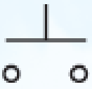
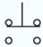
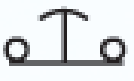
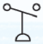
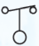
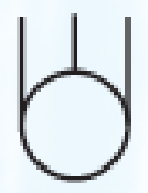
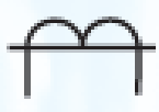
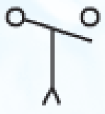
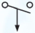
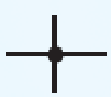
Identify the following symbols.


Expert Solution & Answer
To determine
Identify the given symbols.
Explanation of Solution
Discussion:
The names of the symbols are provided in Table 1.
Table 1
| Part | Name of the symbol | Description |
| a. | Normally open, momentary contact push button. | It is a type of push button, through which two contacts are closed or opened at a time. |
| b. | Double-acting, momentary contact push button. | It is a type of push button, through which two operations can be performed using single push button. |
| c. | Mushroom head, normally closed, momentary contact push button. | It is a palm operated push button. |
| d. | Normally open pressure switch. | It is a type of pressure control relay. |
| e. | Normally closed float switch. | It is a type of pilot devices. It controls the circuit through single contact. |
| f. | Three-phase squirrel cage motor. | It is a type of motor. |
| g. | Current transformer. | It is a type of transformer that is mostly used in large motor starters to step down the current. |
| h. | Three-phase disconnect switch. | It is a type of switch that is used to disconnect the three phases from supply. |
| i. | Normally open contact. | It is a type of switch, in which no current flows in the circuit. |
| j. | Normally open, on-delay timer contact. | It is a type of timed contacts. |
| k. | Normally open, off-delay timer contact. | It is a type of timed contacts. |
| l. | Normally open limit switch. | It is a type of limit switch. |
| m. | Node point showing connected conductors. | It is a point at which two or more conductors are connected. |
| n. | Red pilot light. | It is mostly used for the indication of pilot lights. |
| o. | Normally open switch (single-pole single-throw switch). | It is a type of switch. By single throw, the switch can be either opened or closed. |
| p. | Double-break switch. | It is a type of switch, in which two contacts are to be opened or closed at a time. |
Conclusion:
Thus, the names for the given symbols are provided.
Want to see more full solutions like this?
Subscribe now to access step-by-step solutions to millions of textbook problems written by subject matter experts!
Students have asked these similar questions
During the lab you will design and measure a differential amplifier, made with an opamp.
inside generator
R5
ww
500
V1
0.1Vpk
1kHz
0°
R6
w
50Ω
R1
ww
10ΚΩ
VCC
C1
balanced wire
R3
w
15.0V
signal+
100nF U1A
TL082CP
ground
2
signal-
R4
w
C2
Question5: Calculate R3 and R4 for a 20dB.
100nF
VEE
-15.0V
R2
ww
10ΚΩ
not use ai please
3. Consider the system described by the transfer function Gp(s)
polynomial controller to satisfy the below specifications:
1) The settling time is t = 1 second,
2) 0.1% peak overshoot,
3) and zero steady-state error
for a ramp input. The sampling period is T = 0.01 second.
1
=
Design a discrete-time
s(s+5)*
Chapter 4 Solutions
Electric Motor Control
Ch. 4 - Identify the following symbols.Ch. 4 - Electrical symbols usually conform to which...Ch. 4 - What do the following abbreviations stand for? a....Ch. 4 - Single-pole and double-pole switch symbols are...Ch. 4 - The symbol shown is a a. polarized capacitor. b....Ch. 4 - The symbol shown is a a. normally closed float...Ch. 4 - The symbol shown is a(n) a. iron core transformer....Ch. 4 - The symbol shown is a a. normally open pressure...Ch. 4 - The symbol shown is a a. double-acting push...Ch. 4 - If you were installing the circuit in Figure 412,...
Knowledge Booster


Learn more about
Need a deep-dive on the concept behind this application? Look no further. Learn more about this topic, electrical-engineering and related others by exploring similar questions and additional content below.Similar questions
- Problem 2 Does there exist a value a that makes the two systems S₁ and S₂ equal? If so, what is this value ? If not, explain why. S₁ x[n] x[n] D D -2 → host 回洄 S with h[m] " 999. усиз -1012345 harrow_forwardplease not use any aiarrow_forwardProblem 2 Does there exist a value a that makes the two systems S₁ and S₂ equal? If so, what is this value ? If not, explain why. S₁ x[n] x[n] D D -2 → host 回洄 S with h[m] " 999. усиз -1012345 harrow_forward
- Solve only no 8, Don't use chatgpt or any , only expertarrow_forwardI need help in creating a matlab code to find the currents USING MARTIXS AND INVERSE to find the currentarrow_forwardQuestion 2 A transistor is used as a switch and the waveforms are shown in Figure 2. The parameters are Vcc = 225 V, VBE(sat) = 3 V, IB = 8 A, VCE(sat) = 2 V, Ics = 90 A, td = 0.5 µs, tr = 1 µs, ts = 3 µs, tƒ = 2 μs, and f 10 kHz. The duty cycle is k 50%. The collector- emitter leakage current is ICEO = 2 mA. Determine the power loss due to the collector current: = = = (a) during turn-on ton = td + tr VCE Vcc (b) during conduction period tn V CE(sat) 0 toff" ton Ics 0.9 Ics (c) during turn-off toff = ts + tf (d) during off-time tot (e) the total average power losses PT ICEO 0 IBS 0 Figure 2 V BE(sat) 0 主 * td tr In Is If to iB VBE T= 1/fsarrow_forward
- Question 1: The beta (B) of the bipolar transistor shown in Figure 1 varies from 12 to 60. The load resistance is Rc = 5. The dc supply voltage is VCC = 40 V and the input voltage to the base circuit is VB = 5 V. If VCE(sat) = 1.2 V, VBE(sat) = 1.6 V, and RB = 0.8 2, calculate: (a) the overdrive factor ODF. (b) the forced ẞ (c) the power loss in the transistor PT. IB VB RB + V BE RC Vcc' Ic + IE Figure 1 VCEarrow_forwardI need help in creating a matlab code to find the currentsarrow_forwardI need help fixing this MATLAB code: as I try to get it working there were some problems:arrow_forward
- I need help in construct a matlab code to find the voltage of VR1 to VR4, the currents, and the watts based on that circuit.arrow_forwardQ2: Using D flip-flops, design a synchronous counter. The counter counts in the sequence 1,3,5,7, 1,7,5,3,1,3,5,7,.... when its enable input x is equal to 1; otherwise, the counter count 0.arrow_forwardFrom the collector characteristic curves and the dc load line given below, determine the following: (a) Maximum collector current for linear operation (b) Base current at the maximum collector current (c) VCE at maximum collector current. lc (mA) 600 ΜΑ 60- 500 με 50- 400 με 40- 300 μ Α 30- Q-point 200 ΜΑ 20- 10- 100 μ Α 0 VCE (V) 1 2 3 4 5 6 7 8 9 10 [6 Paarrow_forward
arrow_back_ios
SEE MORE QUESTIONS
arrow_forward_ios
Recommended textbooks for you

 Electricity for Refrigeration, Heating, and Air C...Mechanical EngineeringISBN:9781337399128Author:Russell E. SmithPublisher:Cengage Learning
 EBK ELECTRICAL WIRING RESIDENTIALElectrical EngineeringISBN:9781337516549Author:SimmonsPublisher:CENGAGE LEARNING - CONSIGNMENT
 Delmar's Standard Textbook Of ElectricityElectrical EngineeringISBN:9781337900348Author:Stephen L. HermanPublisher:Cengage Learning
Electricity for Refrigeration, Heating, and Air C...
Mechanical Engineering
ISBN:9781337399128
Author:Russell E. Smith
Publisher:Cengage Learning
EBK ELECTRICAL WIRING RESIDENTIAL
Electrical Engineering
ISBN:9781337516549
Author:Simmons
Publisher:CENGAGE LEARNING - CONSIGNMENT
Delmar's Standard Textbook Of Electricity
Electrical Engineering
ISBN:9781337900348
Author:Stephen L. Herman
Publisher:Cengage Learning
Digital modulation: ASK, FSK, and PSK; Author: Sunny Classroom;https://www.youtube.com/watch?v=qGwUOvErR8Q;License: Standard Youtube License