Concept explainers
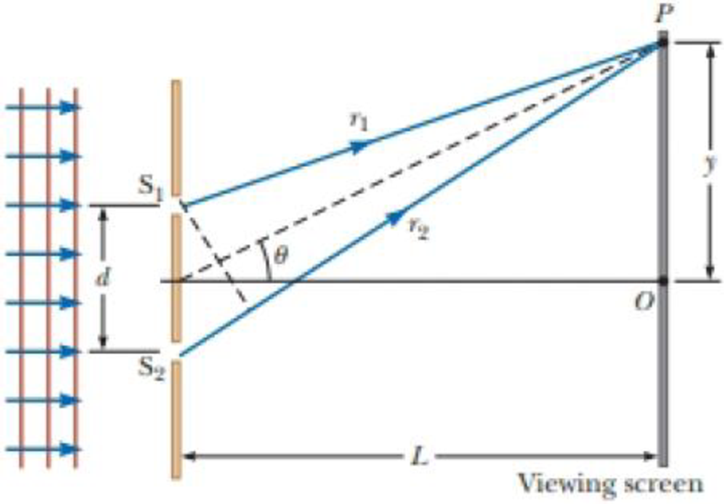
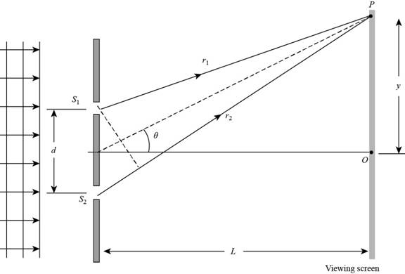
In Figure P36.10 (not to scale), let L = 1.20 m and d = 0.120 mm and assume the slit system is illuminated with monochromatic 500-nm light. Calculate the phase difference between the two wave fronts arriving at P when (a) θ = 0.500° and (b) y = 5.00 mm. (c) What is the value of θ for which the phase difference is 0.333 rad? (d) What is the value of θ for which the path difference is λ/4?
Figure P36.10

(a)
The phase difference between the two waves fronts arriving at
Answer to Problem 10P
The phase difference between the two waves fronts arriving at
Explanation of Solution
Given info: The separation between the slits is
The given diagram is shown below.

Figure 1
The formula to calculate the phase difference is,
Here,
Substitute
Conclusion:
Therefore, the phase difference between the two waves fronts arriving at
(b)
The phase difference between the two waves fronts arriving at
Answer to Problem 10P
The phase difference between the two waves fronts arriving at
Explanation of Solution
Given info: The separation between the slits is
The formula to calculate the phase difference is,
Here,
From the right angle triangle
Here,
Substitute
Substitute
Conclusion:
Therefore, the phase difference between the two waves fronts arriving at
(c)
The value of
Answer to Problem 10P
The value of
Explanation of Solution
Given info: The separation between the slits is
The formula to calculate the phase difference is,
Here,
Rearrange the above formula to find
Substitute
Conclusion:
Therefore, the value of
(d)
The value of
Answer to Problem 10P
The value of
Explanation of Solution
Given info: The separation between the slits is
The formula to calculate the phase difference is,
Here,
The path difference is
Substitute
Rearrange the equation (1) to find
Substitute
Conclusion:
Therefore, the value of
Want to see more full solutions like this?
Chapter 36 Solutions
Bundle: Physics For Scientists And Engineers With Modern Physics, 10th + Webassign Printed Access Card For Serway/jewett's Physics For Scientists And Engineers, 10th, Multi-term
- please help me solve this questions. show all calculations and a good graph too :)arrow_forwardWhat is the force (in N) on the 2.0 μC charge placed at the center of the square shown below? (Express your answer in vector form.) 5.0 με 4.0 με 2.0 με + 1.0 m 1.0 m -40 με 2.0 μCarrow_forwardWhat is the force (in N) on the 5.4 µC charge shown below? (Express your answer in vector form.) −3.1 µC5.4 µC9.2 µC6.4 µCarrow_forward
- An ideal gas in a sealed container starts out at a pressure of 8900 N/m2 and a volume of 5.7 m3. If the gas expands to a volume of 6.3 m3 while the pressure is held constant (still at 8900 N/m2), how much work is done by the gas? Give your answer as the number of Joules.arrow_forwardThe outside temperature is 25 °C. A heat engine operates in the environment (Tc = 25 °C) at 50% efficiency. How hot does it need to get the high temperature up to in Celsius?arrow_forwardGas is compressed in a cylinder creating 31 Joules of work on the gas during the isothermal process. How much heat flows from the gas into the cylinder in Joules?arrow_forward
- The heat engine gives 1100 Joules of energy of high temperature from the burning gasoline by exhausting 750 Joules to low-temperature . What is the efficiency of this heat engine in a percentage?arrow_forwardL₁ D₁ L₂ D2 Aluminum has a resistivity of p = 2.65 × 10 8 2. m. An aluminum wire is L = 2.00 m long and has a circular cross section that is not constant. The diameter of the wire is D₁ = 0.17 mm for a length of L₁ = 0.500 m and a diameter of D2 = 0.24 mm for the rest of the length. a) What is the resistance of this wire? R = Hint A potential difference of AV = 1.40 V is applied across the wire. b) What is the magnitude of the current density in the thin part of the wire? Hint J1 = c) What is the magnitude of the current density in the thick part of the wire? J₂ = d) What is the magnitude of the electric field in the thin part of the wire? E1 = Hint e) What is the magnitude of the electric field in the thick part of the wire? E2 =arrow_forwardplease helparrow_forward
 Principles of Physics: A Calculus-Based TextPhysicsISBN:9781133104261Author:Raymond A. Serway, John W. JewettPublisher:Cengage Learning
 Physics for Scientists and Engineers: Foundations...PhysicsISBN:9781133939146Author:Katz, Debora M.Publisher:Cengage Learning
 Physics for Scientists and Engineers with Modern ...PhysicsISBN:9781337553292Author:Raymond A. Serway, John W. JewettPublisher:Cengage Learning
 Physics for Scientists and EngineersPhysicsISBN:9781337553278Author:Raymond A. Serway, John W. JewettPublisher:Cengage Learning
 Glencoe Physics: Principles and Problems, Student...PhysicsISBN:9780078807213Author:Paul W. ZitzewitzPublisher:Glencoe/McGraw-Hill
 University Physics Volume 3PhysicsISBN:9781938168185Author:William Moebs, Jeff SannyPublisher:OpenStax


