
Concept explainers
Videos
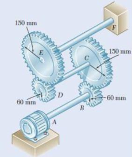
Three shafts and four gears are used to form a gear train that will transmit power from the motor at A to a machine tool at F. (Bearings for the shafts are omitted in the sketch.) The diameter of each shaft is as follows: dAB = 16mm, dCD = 20 mm, dEF = 28 mm. Knowing that the frequency of the motor is 24 Hz and that the allowable shearing stress for each shaft is 75 MPa, determine the maximum power that can be transmitted.
The maximum power that can be transmitted by shaft.
Answer to Problem 74P
The maximum power that can be transmitted by the shaft is
Explanation of Solution
Given information:
The frequency of the motor is 24 Hz.
The allowable shearing stress in each shaft is 75 MPa.
The diameter of the shaft AB is
The diameter of the shaft CD is
The diameter of the shaft EF is
Calculation:
The maximum shear stress in the shaft
Here, T is the torque transmitted by the shaft, c is the radius of the shaft, and J is the polar moment of inertia of the shaft.
The power transmitted by the shaft
For shaft AB:
The polar moment of inertia of shaft AB with radius
Substitute 75 MPa for
The frequency of the shaft AB is
Substitute
For shaft CD:
The polar moment of inertia of shaft CD with radius
Substitute 75 MPa for
The radius at gear B is
The radius at gear C is
The frequency of the shaft CD is,
Substitute
For shaft EF:
The polar moment of inertia of shaft EF with radius
Substitute 75 MPa for
The radius at gear D is
The radius at gear E is
The frequency of the shaft EF is,
Substitute
The maximum allowable power is the smallest value calculated among the shafts AB, CD, and EF.
The allowable power
Therefore, the maximum power that can be transmitted by the shaft is
Want to see more full solutions like this?
Chapter 3 Solutions
EBK MECHANICS OF MATERIALS


- A mass of ideal gas in a closed piston-cylinder system expands from 427 °C and 16 bar following the process law, pv1.36 = Constant (p times v to the power of 1.36 equals to a constant). For the gas, initial : final pressure ratio is 4:1 and the initial gas volume is 0.14 m³. The specific heat of the gas at constant pressure, Cp = 0.987 kJ/kg-K and the specific gas constant, R = 0.267 kJ/kg.K. Determine the change in total internal energy in the gas during the expansion. Enter your numerical answer in the answer box below in KILO JOULES (not in Joules) but do not enter the units. (There is no expected number of decimal points or significant figures).arrow_forwardmy ID# 016948724. Please solve this problem step by steparrow_forwardMy ID# 016948724 please find the forces for Fx=0: fy=0: fz=0: please help me to solve this problem step by steparrow_forward
- My ID# 016948724 please solve the proble step by step find the forces fx=o: fy=0; fz=0; and find shear moment and the bending moment diagran please draw the diagram for the shear and bending momentarrow_forwardMy ID#016948724. Please help me to find the moment of inertia lx ly are a please show to solve step by stepsarrow_forwardplease solve this problem step by steparrow_forward
- Please do not use any AI tools to solve this question. I need a fully manual, step-by-step solution with clear explanations, as if it were done by a human tutor. No AI-generated responses, please.arrow_forwardPlease do not use any AI tools to solve this question. I need a fully manual, step-by-step solution with clear explanations, as if it were done by a human tutor. No AI-generated responses, please.arrow_forwardPlease do not use any AI tools to solve this question. I need a fully manual, step-by-step solution with clear explanations, as if it were done by a human tutor. No AI-generated responses, please.arrow_forward
 Mechanics of Materials (MindTap Course List)Mechanical EngineeringISBN:9781337093347Author:Barry J. Goodno, James M. GerePublisher:Cengage Learning
 International Edition---engineering Mechanics: St...Mechanical EngineeringISBN:9781305501607Author:Andrew Pytel And Jaan KiusalaasPublisher:CENGAGE L
 Principles of Heat Transfer (Activate Learning wi...Mechanical EngineeringISBN:9781305387102Author:Kreith, Frank; Manglik, Raj M.Publisher:Cengage Learning
 Precision Machining Technology (MindTap Course Li...Mechanical EngineeringISBN:9781285444543Author:Peter J. Hoffman, Eric S. Hopewell, Brian JanesPublisher:Cengage Learning
 Automotive Technology: A Systems Approach (MindTa...Mechanical EngineeringISBN:9781133612315Author:Jack Erjavec, Rob ThompsonPublisher:Cengage Learning