
Concept explainers
Videos
A 4-m-long steel member has a W310 × 60 cross section. Knowing that G = 77.2 GPa and that the allowable shearing stress is 40 MPa, determine (a) the largest torque T that can be applied, (b) the corresponding angle of twist. Refer to Appendix C for the dimensions of the cross section and neglect the effect of stress concentrations. (Hint: consider the web and flanges separately and obtain a relation between the torques exerted on the web and a flange, respectively, by expressing that the resulting angles of twist are equal.)
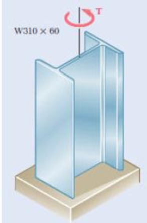
Fig. P3.137
(a)
Find the largest torque (T) that can be applied.
Answer to Problem 137P
The largest torque (T) is
Explanation of Solution
Given information:
The length of the steel member (L) is
The provided section of the member is
The allowable shearing stress
The modulus rigidity of the steel (G) is
Assume the angle of twist in flange and web is equal.
Calculation:
Consider flange:
Refer Appendix C, “Properties of Rolled-Steel shapes”.
The width of the flange (a) is
The thickness of the flange (b) is
Calculate the ratio of width to thickness of the steel
Substitute
Hence, the ratio of
Calculate the ratio of thickness to width of the steel
Substitute
Calculate the coefficient for rectangular bar
Substitute 0.0645 for
Calculate the angle of twist in flange
Here,
Substitute 0.31979 for
Consider web:
Refer Appendix C, “Properties of Rolled-Steel shapes”.
The thickness of the web (b) is
The depth of the member (D) is
Calculate the width of the web (a) using the formula:
Here,
Substitute
Calculate the ratio of width to thickness of the steel
Substitute
Hence, the ratio of
Calculate the ratio of thickness to width of the steel
Substitute
Calculate the coefficient for rectangular bar
Substitute 0.02716 for
Calculate the angle of twist in web
Substitute 0.32763 for
Since the angle of twist in flange and web is equal, therefore,
Substitute
By taking the sum of torque exerted on two flanges and web in the member is equal to the total torque T applied to member. Therefore,
Substitute
Substitute
Calculate the torque in the flange
Substitute
Substitute
Calculate the torque in the web
Substitute
Substitute
Hence, take the lesser value from the torque produced in flange and web respectively.
Therefore, the largest torque (T) is
(b)
Find the angle
Answer to Problem 137P
The angle
Explanation of Solution
Given information:
The length of the steel member (L) is
The provided section of the member is
The allowable shearing stress
The modulus rigidity of the steel (G) is
Assume the angle of twist in flange and web is equal.
Calculation:
From the above calculation of angle of twist, take the critical angle to compute the angle of twist.
Calculate the angle of twist
Substitute
Therefore, the angle of twist of the section is
Want to see more full solutions like this?
Chapter 3 Solutions
EBK MECHANICS OF MATERIALS


- (read image) (answer given)arrow_forward11-5. Compute all the dimensional changes for the steel bar when subjected to the loads shown. The proportional limit of the steel is 230 MPa. 265 kN 100 mm 600 kN 25 mm thickness X Z 600 kN 450 mm E=207×103 MPa; μ= 0.25 265 kNarrow_forwardT₁ F Rd = 0.2 m md = 2 kg T₂ Tz1 Rc = 0.4 m mc = 5 kg m = 3 kgarrow_forward
- 2. Find a basis of solutions by the Frobenius method. Try to identify the series as expansions of known functions. (x + 2)²y" + (x + 2)y' - y = 0 ; Hint: Let: z = x+2arrow_forward1. Find a power series solution in powers of x. y" - y' + x²y = 0arrow_forward3. Find a basis of solutions by the Frobenius method. Try to identify the series as expansions of known functions. 8x2y" +10xy' + (x 1)y = 0 -arrow_forward
- Hello I was going over the solution for this probem and I'm a bit confused on the last part. Can you please explain to me 1^4 was used for the Co of the tubular cross section? Thank you!arrow_forwardBlood (HD = 0.45 in large diameter tubes) is forced through hollow fiber tubes that are 20 µm in diameter.Equating the volumetric flowrate expressions from (1) assuming marginal zone theory and (2) using an apparentviscosity for the blood, estimate the marginal zone thickness at this diameter. The viscosity of plasma is 1.2 cParrow_forwardQ2: Find the shear load on bolt A for the connection shown in Figure 2. Dimensions are in mm Fig. 2 24 0-0 0-0 A 180kN (10 Markarrow_forward
- determine the direction and magnitude of angular velocity ω3 of link CD in the four-bar linkage using the relative velocity graphical methodarrow_forwardFour-bar linkage mechanism, AB=40mm, BC=60mm, CD=70mm, AD=80mm, =60°, w1=10rad/s. Determine the direction and magnitude of w3 using relative motion graphical method. A B 2 3 77777 477777arrow_forwardFour-bar linkage mechanism, AB=40mm, BC=60mm, CD=70mm, AD=80mm, =60°, w1=10rad/s. Determine the direction and magnitude of w3 using relative motion graphical method. A B 2 3 77777 477777arrow_forward
 Elements Of ElectromagneticsMechanical EngineeringISBN:9780190698614Author:Sadiku, Matthew N. O.Publisher:Oxford University Press
 Mechanics of Materials (10th Edition)Mechanical EngineeringISBN:9780134319650Author:Russell C. HibbelerPublisher:PEARSON
 Thermodynamics: An Engineering ApproachMechanical EngineeringISBN:9781259822674Author:Yunus A. Cengel Dr., Michael A. BolesPublisher:McGraw-Hill Education
 Control Systems EngineeringMechanical EngineeringISBN:9781118170519Author:Norman S. NisePublisher:WILEY
 Mechanics of Materials (MindTap Course List)Mechanical EngineeringISBN:9781337093347Author:Barry J. Goodno, James M. GerePublisher:Cengage Learning
 Engineering Mechanics: StaticsMechanical EngineeringISBN:9781118807330Author:James L. Meriam, L. G. Kraige, J. N. BoltonPublisher:WILEY