
Concept explainers
(i)
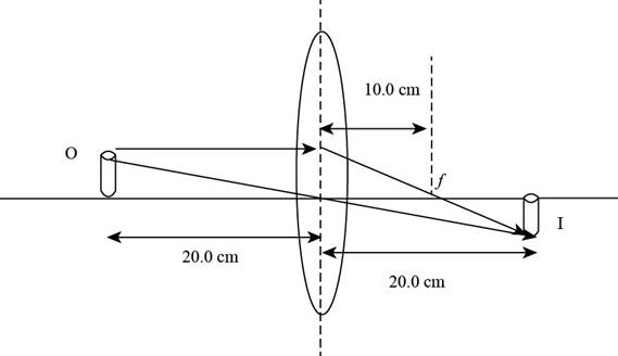
To draw: The ray diagram for the given focal lengthy of the lens and the given object distance.
(i)
Answer to Problem 26P
The ray diagram of the given criteria is,
Explanation of Solution
Introduction:
In a ray diagram in the case of lens or mirror the image is formed where two at least refracted or reflected rays coincide with each other.
Given info: The position of object is at
The ray diagram is shown in the figure below.
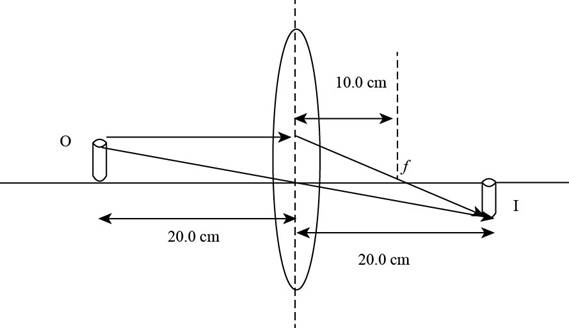
Figure (1)
(ii)
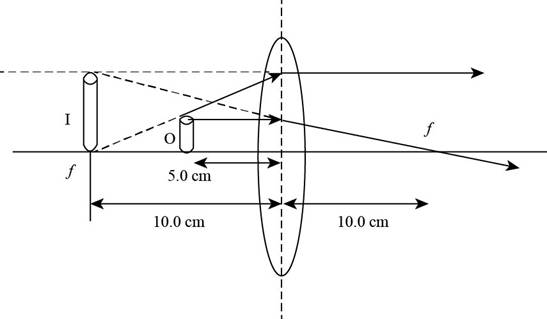
To draw: The ray diagram for the given focal length of the lens and the given object distance.
(ii)
Answer to Problem 26P
The ray diagram of the given criteria is,
Explanation of Solution
Introduction:
In a ray diagram in the case of lens or mirror the image is formed where two at least refracted or reflected rays coincide with each other.
Given info: The position of object is at
The ray diagram is shown in the figure below.
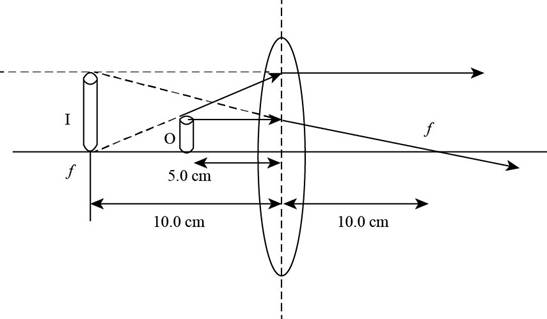
Figure (2)
(a)
The location of the image the given cases.
(a)
Answer to Problem 26P
The image is at
Explanation of Solution
From Figure (1), it is evident that the image is formed on the rear end of the lens and the image distance measured is
From Figure (2), the image is formed at
Conclusion:
Therefore, the measured distance for the image for the case when object is at
(b)
The image is real or virtual.
(b)
Answer to Problem 26P
For the case when object is at
Explanation of Solution
From Figure (1), it is evident that the image is formed on the rear side and is real and the images formed at the back side of the lens are real.
From Figure (2), the image is formed at
Conclusion:
The images formed by the lens in front of it are virtual and erect and images formed on the back side are real and inverted. Hence, image formed by the object kept at.
(c)
The image is upright or inverse.
(c)
Answer to Problem 26P
For the case when object is at
Explanation of Solution
From Figure (1), it is evident that the image is formed on the rear side and is real. and
the real images are always inverted
From Figure (2), the image is formed at
The virtual images are always upright.
Conclusion:
Therefore, the images formed by the lens in front of it are virtual and erect and images formed on the back side are real and inverted. Hence, image formed by the object kept at.
(d)
The magnification of the image.
(d)
Answer to Problem 26P
For the case when object is at
Explanation of Solution
From Figure (1) it is evident that the image is formed on the rear side and is real and inverted the object height is
Formula to calculate the magnification is
For the object at
For the object at the distance of
Conclusion:
Therefore, for the case of object at
(e)
The difference between the value of the ray diagram and the algebraic calculation.
(e)
Answer to Problem 26P
The value obtained from the ray diagrams for the cases are same for the values obtained in the algebraic calculation.
Explanation of Solution
Given Info: The focal length of the give lens is
From Figure (1) the image distance for the object at
For algebraic calculation, the formula for the image distance is,
Here,
Substitute
Form figure (1) the magnification is
Formula to calculate the magnification of the image
Here
Substitute
From figure (2) the image distance is
From equation (4) formula to calculate the image distance is,
Substitute
The image distance is
From equation (6) the formula to calculate the magnification is,
Substitute
From equation (6) and equation (7) it is evident that for the case of object at
From equation (8) and (9) the image distance and magnification is same for the ray diagram and the algebraic case when the object is
Conclusion:
Therefore, the result for the ray diagrams and algebraic calculations are same.
(f)
The difficulties is making the graph which may lead to difference between the algebraic and graphical values.
(f)
Answer to Problem 26P
Human hand errors, Parallax errors and scale measurement errors could lead to difference in the values of graph and algebraic calculation.
Explanation of Solution
While drawing the graph the possible errors are human hand errors, parallax errors and scale measurement errors.
Human Hand Errors are while making the ray diagrams the rays might not converge with extreme precision. Parallax error/Human eye errors occur due to human eye. Scale errors are during the scale measurement.
Conclusion:
Therefore, the three most common errors that can lead to difficulties in constructing the graph which might lead to change the algebraic and graphical values are human hand errors, parallax errors and Scale errors.
Want to see more full solutions like this?
Chapter 35 Solutions
Physics for Scientists and Engineers with Modern Physics
- Pls help asaparrow_forward3. If the force of gravity stopped acting on the planets in our solar system, what would happen? a) They would spiral slowly towards the sun. b) They would continue in straight lines tangent to their orbits. c) They would continue to orbit the sun. d) They would fly straight away from the sun. e) They would spiral slowly away from the sun. 4. 1 The free-body diagram of a wagon being pulled along a horizontal surface is best represented by A F N B C 0 Ꭰ FN E a) A b) B c) C app app The app 10 app d) e) ס ח D E 10 apparrow_forwardPls help ASAParrow_forward
- Pls help asaparrow_forwardPls help asaparrow_forwardThe acceleration of an object sliding along a frictionless ramp is inclined at an angle 0 is 9. a) g tano b) g cose c) g sino 10. d) g e) zero A 1.5 kg cart is pulled with a force of 7.3 N at an angle of 40° above the horizontal. If a kinetic friction force of 3.2 N acts against the motion, the cart's acceleration along the horizontal surface will be a) 5.0 m/s² b) 1.6 m/s² c) 2.4 m/s² 11. d) 1.0 m/s² e) 2.7 m/s² What is the net force acting on an object with a mass of 10 kg moving at a constant velocity of 10 m/s [North]? a) 100 N [North] b) 100 N [South] 10 N [North} d) 10 N [South] e) None of these.arrow_forward
- Modified True/False - indicate whether the sentence or statement is true or false. If the statement is false, correct the statement to make it true. 12. An object in uniform circular motion has a constant velocity while experiencing centripetal acceleration. 13. An object travelling in uniform circular motion experiences an outward centrifugal force that tends to pull the object out of the circular path. 14. An object with less inertia can resist changes in motion more than an object with more inertia. 15. For an object sliding on a horizontal surface with a horizontal applied force, the frictional force will always increase as the applied force increases.arrow_forwardPls help asaparrow_forwardAnswer the given question showing step by step by and all necessary working out.arrow_forward
 Principles of Physics: A Calculus-Based TextPhysicsISBN:9781133104261Author:Raymond A. Serway, John W. JewettPublisher:Cengage Learning
 Physics for Scientists and Engineers: Foundations...PhysicsISBN:9781133939146Author:Katz, Debora M.Publisher:Cengage Learning
 University Physics Volume 3PhysicsISBN:9781938168185Author:William Moebs, Jeff SannyPublisher:OpenStax
 Physics for Scientists and EngineersPhysicsISBN:9781337553278Author:Raymond A. Serway, John W. JewettPublisher:Cengage Learning
 Physics for Scientists and Engineers with Modern ...PhysicsISBN:9781337553292Author:Raymond A. Serway, John W. JewettPublisher:Cengage Learning
 Physics for Scientists and Engineers, Technology ...PhysicsISBN:9781305116399Author:Raymond A. Serway, John W. JewettPublisher:Cengage Learning


