
Engineering Mechanics: Statics and Modified Mastering Engineering with eText and Access Card (14th Edition)
14th Edition
ISBN: 9780134229287
Author: Russell C. Hibbeler
Publisher: PEARSON
expand_more
expand_more
format_list_bulleted
Concept explainers
Videos
Textbook Question
Chapter 3.4, Problem 53P
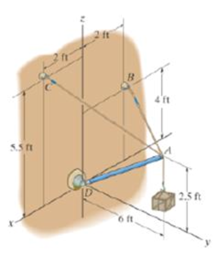
Also, what is the force developed along strut AD?
Expert Solution & Answer
Want to see the full answer?
Check out a sample textbook solution
Students have asked these similar questions
Qu 3 Nickel (Ni) single crystal turbine blades burn less fuel at higher temperatures because blades are grown on [110] closed packed direction. Nickel (Ni) at 20°C is FCC, and has an atomic radius, R, of 0.125 nm. Draw a reduced-sphere unit cell for this crystal and draw and label the vector [I 10], starting from the origin (0, 0, 0).
a) Calculate the length of the vector [| 10] in nanometers. Express your answer in nanometers to one significant figure.
b) Calculate the linear density of Nickel in the [| 1 0] direction in [atom/nm]. Express your answer in atoms/nm to one significant figure.
show all work problems
handwritten-solutions, please!
handwritten-solutions, please!
Chapter 3 Solutions
Engineering Mechanics: Statics and Modified Mastering Engineering with eText and Access Card (14th Edition)
Ch. 3.3 - In each case, draw a free-body diagram of the ring...Ch. 3.3 - Do not solve.Ch. 3.3 - Determine the force in each supporting cable.Ch. 3.3 - Determine the shortest cable ABC that can be used...Ch. 3.3 - Neglect the size of the pulley.Ch. 3.3 - Determine the unstretched length of the spring.Ch. 3.3 - If the mass of cylinder C is 40 kg, determine the...Ch. 3.3 - Also, find the angle .Ch. 3.3 - Determine the magnitudes of F1 and F2 for...Ch. 3.3 - Determine the magnitude of F1 and its angle for...
Ch. 3.3 - Determine the magnitude and direction of F so...Ch. 3.3 - The bottom one is subjected to a 125-N force at...Ch. 3.3 - If the forces are concurrent at point O, determine...Ch. 3.3 - Determine the tension force in member C and its...Ch. 3.3 - If the tension in AB is 60 lb, determine the...Ch. 3.3 - The cords ABC and BD can each support a maximum...Ch. 3.3 - Determine the maximum force F that can be...Ch. 3.3 - Determine the angle for equilibrium and the force...Ch. 3.3 - Prob. 11PCh. 3.3 - Determine the force in each of the cables AB and...Ch. 3.3 - Prob. 13PCh. 3.3 - The springs are shown in the equilibrium position.Ch. 3.3 - If the block is held in the equilibrium position...Ch. 3.3 - Note that s = 0 when the cylinders are removed.Ch. 3.3 - Prob. 17PCh. 3.3 - determine the stiffness of the spring to hold the...Ch. 3.3 - Take k = 180 N/m.Ch. 3.3 - If the spring has an unstretched length of 2 ft,...Ch. 3.3 - Cord AB is 2 ft long. Take k = 50 lb/ft.Ch. 3.3 - Determine the horizontal force F applied to the...Ch. 3.3 - Determine the displacement d of the cord from the...Ch. 3.3 - Determine the distances x and y for equilibrium if...Ch. 3.3 - Determine the magnitude of F1 and the distance y...Ch. 3.3 - Determine the force in each cord for equilibrium.Ch. 3.3 - Determine the largest mass of pipe that can be...Ch. 3.3 - If each light has a weight of 50 lb. determine the...Ch. 3.3 - Determine the tension developed in each cord...Ch. 3.3 - Determine the maximum mass of the lamp that the...Ch. 3.3 - If x = 2 m determine the force F and the sag s for...Ch. 3.3 - If F = 80 N. determine the sag s and distance x...Ch. 3.3 - Determine the tension in each cord and the angle ...Ch. 3.3 - Determine the largest weight of the lamp that can...Ch. 3.3 - Also, what is the force in cord AB? Hint: use the...Ch. 3.3 - Determine the position x and the tension developed...Ch. 3.3 - Prob. 37PCh. 3.3 - Take F = 300 N and d = 1 m.Ch. 3.3 - If a force of F = 100 N is applied horizontally to...Ch. 3.3 - If the cable can be attached at either points A...Ch. 3.3 - Determine the position x and the tension in the...Ch. 3.3 - The cord is fixed to a pin at A and passes over...Ch. 3.3 - Establish appropriate dimensions and use an...Ch. 3.3 - If the maximum tension that can be supported by...Ch. 3.3 - If the angle between AB and BC is 30, determine...Ch. 3.3 - If the distance BC is 1.5 m, and AB can support a...Ch. 3.4 - Determine the magnitude of forces F1, F2, F3, so...Ch. 3.4 - Determine the tension developed in cables AB, AC,...Ch. 3.4 - Determine the tension developed in cables AB, AC,...Ch. 3.4 - F310. Determine the tension developed in cables...Ch. 3.4 - Determine the tension in these wires.Ch. 3.4 - Determine the force developed in each cable for...Ch. 3.4 - Determine the magnitudes of F1, F2, and F3 for...Ch. 3.4 - If the bucket and its contents have a total weight...Ch. 3.4 - Each spring has on unstretched length of 2 m and a...Ch. 3.4 - Determine the force in each cable needed to...Ch. 3.4 - Determine the tension in the cables in order to...Ch. 3.4 - Determine the maximum mass of the crate so that...Ch. 3.4 - Determine the force in each cable if F = 500 lb.Ch. 3.4 - Determine the greatest force F that can be applied...Ch. 3.4 - Determine the tens on developed in cables AB and...Ch. 3.4 - Also, what is the force developed along strut AD?Ch. 3.4 - Determine the tension developed in each cable for...Ch. 3.4 - Determine the maximum weight of the crate that can...Ch. 3.4 - Prob. 56PCh. 3.4 - If each cord can sustain a maximum tension of 50 N...Ch. 3.4 - which has a mass of 15 kg. Take h = 4 m.Ch. 3.4 - Take h = 3.5 m.Ch. 3.4 - Determine the force in each chain for equilibrium....Ch. 3.4 - Determine the tension in each cable for...Ch. 3.4 - If the maximum force in each rod con not exceed...Ch. 3.4 - Determine the tension developed in each cable for...Ch. 3.4 - If cable AD is tightened by a turnbuckle and...Ch. 3.4 - If cable AD is tightened by a turnbuckle and...Ch. 3.4 - Determine the tension developed in cables AB, AC,...Ch. 3.4 - Determine the maximum weight of the crate so that...Ch. 3.4 - If the bolt exerts a force of 50 lb on the pipe in...Ch. 3.4 - Prob. 2RPCh. 3.4 - Determine the maximum weight of the flowerpot that...Ch. 3.4 - Determine the magnitude of the applied vertical...Ch. 3.4 - Prob. 5RPCh. 3.4 - Determine the magnitudes of F1, F2, and F3 for...Ch. 3.4 - Determine the force in each cable needed to...Ch. 3.4 - If cable AB is subjected to a tension of 700 N,...
Knowledge Booster


Learn more about
Need a deep-dive on the concept behind this application? Look no further. Learn more about this topic, mechanical-engineering and related others by exploring similar questions and additional content below.Similar questions
- Required information An eccentric force P is applied as shown to a steel bar of 25 × 90-mm cross section. The strains at A and B have been measured and found to be εΑ = +490 μ εB=-70 μ Know that E = 200 GPa. 25 mm 30 mm 90 mm 45 mm B Determine the distance d. The distance dis 15 mm mm.arrow_forwardhandwritten-solutions, please!arrow_forwardhandwritten-solutions, please!arrow_forward
- ! Required information Assume that the couple shown acts in a vertical plane. Take M = 25 kip.in. r = 0.75 in. A B 4.8 in. M 1.2 in. [1.2 in. Determine the stress at point B. The stress at point B is ksi.arrow_forwardhandwritten-solutions, please!arrow_forwardhandwritten-solutions, please!arrow_forward
- No use chatgptarrow_forwardProblem 6 (Optional, extra 6 points) 150 mm 150 mm 120 mm 80 mm 60 mm PROBLEM 18.103 A 2.5 kg homogeneous disk of radius 80 mm rotates with an angular velocity ₁ with respect to arm ABC, which is welded to a shaft DCE rotating as shown at the constant rate w212 rad/s. Friction in the bearing at A causes ₁ to decrease at the rate of 15 rad/s². Determine the dynamic reactions at D and E at a time when ₁ has decreased to 50 rad/s. Answer: 5=-22.01 +26.8} N E=-21.2-5.20Ĵ Narrow_forwardProblem 1. Two uniform rods AB and CE, each of weight 3 lb and length 2 ft, are welded to each other at their midpoints. Knowing that this assembly has an angular velocity of constant magnitude c = 12 rad/s, determine: (1). the magnitude and direction of the angular momentum HD of the assembly about D. (2). the dynamic reactions (ignore mg) at the bearings at A and B. 9 in. 3 in. 03 9 in. 3 in. Answers: HD = 0.162 i +0.184 j slug-ft²/s HG = 2.21 k Ay =-1.1 lb; Az = 0; By = 1.1 lb; B₂ = 0.arrow_forward
- Problem 5 (Optional, extra 6 points) A 6-lb homogeneous disk of radius 3 in. spins as shown at the constant rate w₁ = 60 rad/s. The disk is supported by the fork-ended rod AB, which is welded to the vertical shaft CBD. The system is at rest when a couple Mo= (0.25ft-lb)j is applied to the shaft for 2 s and then removed. Determine the dynamic reactions at C and D before and after the couple has been removed at 2 s. 4 in. C B Mo 5 in 4 in. Note: 2 rotating around CD induced by Mo is NOT constant before Mo is removed. and ₂ (two unknowns) are related by the equation: ₂ =0+ w₂t 3 in. Partial Answer (after Mo has been removed): C-7.81+7.43k lb D -7.81 7.43 lbarrow_forwardProblem 4. A homogeneous disk with radius and mass m is mounted on an axle OG with length L and a negligible mass. The axle is pivoted at the fixed-point O, and the disk is constrained to roll on a horizontal surface. The disk rotates counterclockwise at the constant rate o₁ about the axle. (mg must be included into your calculation) (a). Calculate the linear velocity of G and indicate it on the figure. (b). Calculate ₂ (constant), which is the angular velocity of the axle OG around the vertical axis. (c). Calculate the linear acceleration ā of G and indicate it on the figure. (d). Determine the force (assumed vertical) exerted by the floor on the disk (e). Determine the reaction at the pivot O. 1 Answers: N = mg +mr(r/L)² @² |j mr w IIG C R L i+ 2L =arrow_forwardProblem 2. The homogeneous disk of weight W = 6 lb rotates at the constant rate co₁ = 16 rad/s with respect to arm ABC, which is welded to a shaft DCE rotating at the constant rate 2 = 8 rad/s. Assume the rod weight is negligible compared to the disk. Determine the dynamic reactions at D and E (ignore mg). Answers: D=-7.12ĵ+4.47k lb r-8 in. 9 in. B D E=-1.822+4.47 lb 9 in. E 12 in. 12 in. xarrow_forward
arrow_back_ios
SEE MORE QUESTIONS
arrow_forward_ios
Recommended textbooks for you
 Welding: Principles and Applications (MindTap Cou...Mechanical EngineeringISBN:9781305494695Author:Larry JeffusPublisher:Cengage Learning
 Mechanics of Materials (MindTap Course List)Mechanical EngineeringISBN:9781337093347Author:Barry J. Goodno, James M. GerePublisher:Cengage Learning
Welding: Principles and Applications (MindTap Cou...
Mechanical Engineering
ISBN:9781305494695
Author:Larry Jeffus
Publisher:Cengage Learning
Mechanics of Materials (MindTap Course List)
Mechanical Engineering
ISBN:9781337093347
Author:Barry J. Goodno, James M. Gere
Publisher:Cengage Learning
Introduction To Engg Mechanics - Newton's Laws of motion - Kinetics - Kinematics; Author: EzEd Channel;https://www.youtube.com/watch?v=ksmsp9OzAsI;License: Standard YouTube License, CC-BY