
Videos
(a)
The equivalent force at end A of the beam by replacing each loading with an equivalent force couple system.
(a)
Answer to Problem 3.101P
The equivalent force and couple at end A of the beam are as below,
For the beam (a), the equivalent force
For the beam (b), the equivalent force
For the beam (c), the equivalent force
For the beam (d), the equivalent force
For the beam (e), the equivalent force
For the beam (f), the equivalent force
For the beam (g), the equivalent force
For the beam (h), the equivalent force
Explanation of Solution
(a)
Draw the free body diagram of the beam (a) as Figure (1).
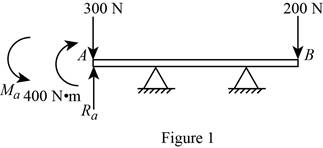
Refer Figure (1).
Calculate the equivalent force at end A
Consider the vertical equilibrium condition.
Calculate the moment about A
Thus, for the beam (a), the equivalent force
(b)
Draw the free body diagram of the beam (b) as Figure (2).
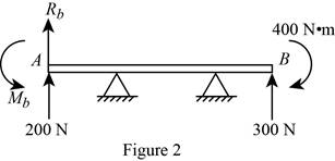
Refer Figure (2).
Calculate the equivalent force at end A
Consider the vertical equilibrium condition.
Calculate the moment about A
Thus, for the beam (b), the equivalent force
(c)
Draw the free body diagram of the beam (c) as Figure (3).
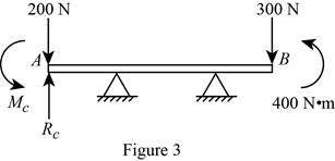
Refer Figure (3).
Calculate the equivalent force at end A
Consider the vertical equilibrium condition.
Calculate the moment about A
Thus, for the beam (c), the equivalent force
(d)
Draw the free body diagram of the beam (d) as Figure (4).
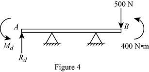
Refer Figure (4).
Calculate the equivalent force at end A
Consider the vertical equilibrium condition.
Calculate the moment about A
Thus, for the beam (d), the equivalent force
(e)
Draw the free body diagram of the beam (e) as Figure (5).
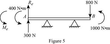
Refer Figure (5).
Calculate the equivalent force at end A
Consider the vertical equilibrium condition.
Calculate the moment about A
Thus, for the beam (e), the equivalent force
(f)
Draw the free body diagram of the beam (f) as Figure (6).
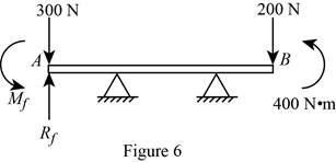
Refer Figure (6).
Calculate the equivalent force at end A
Consider the vertical equilibrium condition.
Calculate the moment about A
Thus, for the beam (f), the equivalent force
(g)
Draw the free body diagram of the beam (g) as Figure (7).
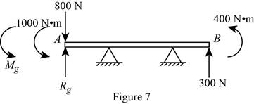
Refer Figure (7).
Calculate the equivalent force at end A
Consider the vertical equilibrium condition.
Calculate the moment about A
Thus, for the beam (g), the equivalent force
(h)
Draw the free body diagram of the beam (h) as Figure 8.
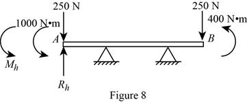
Refer Figure (8).
Calculate the equivalent force at end A
Consider the vertical equilibrium condition.
Calculate the moment about A
Thus, for the beam (h), the equivalent force
(b)
The loading which are equivalent.
(b)
Answer to Problem 3.101P
The loading in all beams are equivalent.
Explanation of Solution
Refer part (a) loading calculation.
The loading condition in the case (a) and (e) are equivalent.
Want to see more full solutions like this?
Chapter 3 Solutions
Connect 1 Semester Access Card for Vector Mechanics for Engineers: Statics and Dynamics


- please help me to solve this problem and determine the stress for each point i like to be explained step by step with the correct answerarrow_forwardplease solve this problem for me the best way that you can explained to solve please show me the step how to solvearrow_forwardplese solbe this problem and give the correct answer solve step by step find the forces and line actionarrow_forward
- please help me to solve this problems first write the line of action and them find the forces {fx=0: fy=0: mz=0: and them draw the shear and bending moment diagram. please explain step by steparrow_forwardplease solve this problem step by step like human and give correct answer step by steparrow_forwardPROBLEM 11: Determine the force, P, that must be exerted on the handles of the bolt cutter. (A) 7.5 N (B) 30.0 N (C) 52.5 N (D) 300 N (E) 325 N .B X 3 cm E 40 cm cm F = 1000 N 10 cm 3 cm boltarrow_forward
- Using the moment-area theorems, determine a) the rotation at A, b) the deflection at L/2, c) the deflection at L/4. (Hint: Use symmetry for Part a (θA= - θB, or θC=0), Use the rotation at A for Parts b and c. Note that all deformations in the scope of our topics are small deformation and for small θ, sinθ=θ).arrow_forwardDistilled water is being cooled by a 20% propylene glycol solution in a 1-1/U counter flow plate and frame heat exchanger. The water enters the heat exchanger at 50°F at a flow rate of 86,000 lbm/h. For safety reasons, the water outlet temperature should never be colder than 35°F. The propylene glycol solution enters the heat exchanger at 28°F with a flow rate of 73,000 lbm/h. The port distances on the heat exchanger are Lv = 35 in and Lh = 18 in. The plate width is Lw = 21.5 2 in. The plate thickness is 0.04 in with a plate pitch of 0.12 in. The chevron angle is 30° and the plate enlargement factor is 1.17. All ports have a 2 in diameter. The fouling factor of the propylene glycol solution can be estimated as 2 ×10⁻⁵ h-ft2-°F/Btu. a. Determine the maximum number of plates the heat exchanger can have while ensuring that the water outlet temperature never drops below 35°F. b. Determine the thermal and hydraulic performance of the heat exchanger with the specified number of plates.…arrow_forwardLiquid pentane is flowing in the shell of a shell and tube heat exchanger at a rate of 350,000lbm/hr and an average temperature of 20°F. The shell has a diameter of 27 in and a length of 16ft. The tubes in the heat exchanger are ¾-in 15 BWG tubes on a 1-in triangular pitch. The purposeof this problem is to investigate how the number of baffles impacts the heat transfer and thepressure drop on the shell side of the heat exchanger. Calculate the shell-side convective heattransfer coefficient and pressure drop for the case where the heat exchanger has 10 baffles. Repeatthe calculation for 20 baffles. Then determine thea. Ratio of the shell-side convective heat transfer coefficient for the 20-baffle heat exchangerto the 10-baffle heat exchangerb. Ratio of the shell-side pressure drop for the 20-baffle heat exchanger to the 10-baffle heatexchangerc. If the optimum baffle spacing is somewhere between 0.4Ds and 0.6Ds, how many baffleswould you recommend for this heat exchanger? What are the…arrow_forward
 Elements Of ElectromagneticsMechanical EngineeringISBN:9780190698614Author:Sadiku, Matthew N. O.Publisher:Oxford University Press
 Mechanics of Materials (10th Edition)Mechanical EngineeringISBN:9780134319650Author:Russell C. HibbelerPublisher:PEARSON
 Thermodynamics: An Engineering ApproachMechanical EngineeringISBN:9781259822674Author:Yunus A. Cengel Dr., Michael A. BolesPublisher:McGraw-Hill Education
 Control Systems EngineeringMechanical EngineeringISBN:9781118170519Author:Norman S. NisePublisher:WILEY
 Mechanics of Materials (MindTap Course List)Mechanical EngineeringISBN:9781337093347Author:Barry J. Goodno, James M. GerePublisher:Cengage Learning
 Engineering Mechanics: StaticsMechanical EngineeringISBN:9781118807330Author:James L. Meriam, L. G. Kraige, J. N. BoltonPublisher:WILEY