Statics and Mechanics of Materials
2nd Edition
ISBN: 9780073398167
Author: Ferdinand P. Beer, E. Russell Johnston Jr., John T. DeWolf, David Mazurek
Publisher: McGraw-Hill Education
expand_more
expand_more
format_list_bulleted
Concept explainers
Videos
Textbook Question
Chapter 3.3, Problem 64P
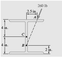
A 260-lb force is applied at A to the rolled-steel section shown. Replace that force with an equivalent force-couple system at the center C of the section.
Expert Solution & Answer
Want to see the full answer?
Check out a sample textbook solution
Students have asked these similar questions
Please solve this problem as soon as possible My ID# 016948724
The gears shown in the figure have a diametral pitch of 2 teeth per inch and a 20° pressure angle.
The pinion rotates at 1800 rev/min clockwise and transmits 200 hp through the idler pair to gear
5 on shaft c. What forces do gears 3 and 4 transmit to the idler shaft?
TS
I
y
18T
32T
This
a
12
x
18T
C
48T
5
Question 1. Draw 3 teeth for the following pinion and gear respectively. The teeth
should be drawn near the pressure line so that the teeth from the pinion should
mesh those of the gear. Drawing scale (1:1). Either a precise hand drawing or
CAD drawing is acceptable. Draw all the trajectories of the involute lines and the
circles.
Specification: 18tooth pinion and 30tooth gear. Diameter pitch=P=6 teeth /inch.
Pressure angle:20°, 1/P for addendum (a) and 1.25/P for dedendum (b). For fillet,
c=b-a.
Chapter 3 Solutions
Statics and Mechanics of Materials
Ch. 3.1 - A 20-lb force is applied to the control rod AB as...Ch. 3.1 - A 20-lb force is applied to the control rod AB as...Ch. 3.1 - A 300-N force P is applied at point A of the bell...Ch. 3.1 - A 400-N force P is applied at point A of the bell...Ch. 3.1 - A 300-N force is applied at A as shown. Determine...Ch. 3.1 - A 300-N force is applied at A as shown. Determine...Ch. 3.1 - 3.7 and 3.8 The tailgate of a car is supported by...Ch. 3.1 - 3.7 and 3.8 The tailgate of a car is supported by...Ch. 3.1 - 3.9 and 3.10 It is known that the connecting rod...Ch. 3.1 - 3.9 and 3.10 It is known that the connecting rod...
Ch. 3.1 - Rod AB is held in place by the cord AC. Knowing...Ch. 3.1 - Prob. 12PCh. 3.1 - Determine the moment about the origin O of the...Ch. 3.1 - Determine the moment about the origin O of the...Ch. 3.1 - Prob. 15PCh. 3.1 - Prob. 16PCh. 3.1 - Prob. 17PCh. 3.1 - A wooden board AB, which is used as a temporary...Ch. 3.1 - Prob. 19PCh. 3.1 - A small boat hangs from two davits, one of which...Ch. 3.1 - Prob. 21PCh. 3.1 - In Prob. 3.16, determine the perpendicular...Ch. 3.1 - In Prob. 3.16, determine the perpendicular...Ch. 3.1 - In Prob. 3.20, determine the perpendicular...Ch. 3.2 - Given the vectors P=3i-j+2k,Q=4i+5j-3k, and...Ch. 3.2 - Prob. 26PCh. 3.2 - Knowing that the tension in cable AC is 1260 N,...Ch. 3.2 - Knowing that the tension in cable AD is 405 N,...Ch. 3.2 - Three cables are used to support a container as...Ch. 3.2 - Three cables are used to support a container as...Ch. 3.2 - The 20-in. tube AB can slide along a horizontal...Ch. 3.2 - Solve Prob. 3.31 for the position corresponding to...Ch. 3.2 - Prob. 33PCh. 3.2 - Prob. 34PCh. 3.2 - Knowing that the tension in cable AB is 570 N,...Ch. 3.2 - Prob. 36PCh. 3.2 - A farmer uses cables and winch pullers B and E to...Ch. 3.2 - Solve Prob. 3.37 when the tension in cable AB is...Ch. 3.2 - To lift a heavy crate, a man uses a block and...Ch. 3.2 - Prob. 40PCh. 3.2 - Prob. 41PCh. 3.2 - Prob. 42PCh. 3.2 - Prob. 43PCh. 3.2 - A sign erected on uneven ground is guyed by cables...Ch. 3.2 - The frame ACD is hinged at and D and is supported...Ch. 3.2 - In Prob. 3.45, determine the moment about the...Ch. 3.2 - Prob. 47PCh. 3.2 - Prob. 48PCh. 3.3 - Two parallel 60-N forces are applied to a lever as...Ch. 3.3 - A plate in the shape of a parallelogram is acted...Ch. 3.3 - Prob. 51PCh. 3.3 - Prob. 52PCh. 3.3 - Four 112-in. -diameter pegs are attached to a...Ch. 3.3 - Prob. 54PCh. 3.3 - Prob. 55PCh. 3.3 - Prob. 56PCh. 3.3 - Replace the two couples shown with a single...Ch. 3.3 - Prob. 58PCh. 3.3 - Shafts A and B connect the gear box to the wheel...Ch. 3.3 - Prob. 60PCh. 3.3 - Prob. 61PCh. 3.3 - The force P has a magnitude of 250 N and is...Ch. 3.3 - Prob. 63PCh. 3.3 - A 260-lb force is applied at A to the rolled-steel...Ch. 3.3 - Prob. 65PCh. 3.3 - A force and couple act as shown on a square plate...Ch. 3.3 - Prob. 67PCh. 3.3 - Prob. 68PCh. 3.3 - Prob. 69PCh. 3.3 - Replace the 150-N force by an equivalent...Ch. 3.3 - Prob. 71PCh. 3.3 - Prob. 72PCh. 3.4 - A 4-m-long beam is subjected to a variety of...Ch. 3.4 - Prob. 74PCh. 3.4 - Determine the single equivalent force and the...Ch. 3.4 - The weights of two children sitting at ends A and...Ch. 3.4 - Prob. 77PCh. 3.4 - Prob. 78PCh. 3.4 - Four forces act on a 700375 -mm plate as shown....Ch. 3.4 - Prob. 80PCh. 3.4 - Prob. 81PCh. 3.4 - A truss supports the loading shown. Determine the...Ch. 3.4 - A machine component is subjected to the forces and...Ch. 3.4 - Solve Prob. 3.83, assuming that P=60N.Ch. 3.4 - Prob. 85PCh. 3.4 - Prob. 86PCh. 3.4 - Prob. 87PCh. 3.4 - Prob. 88PCh. 3.4 - Prob. 89PCh. 3.4 - Assuming e 600 in Prob. 3.89, replace the two...Ch. 3.4 - A blade held in a brace is used to tighten a screw...Ch. 3.4 - Prob. 92PCh. 3.4 - Four signs are mounted on a frame spanning a...Ch. 3.4 - Prob. 94PCh. 3.4 - Prob. 95PCh. 3.4 - Three children are standing on a 55-m raft. The...Ch. 3 - For the shift lever shown, determine the magnitude...Ch. 3 - Consider the volleyball net shown. Determine the...Ch. 3 - A crane is oriented so that the end of the 25-m...Ch. 3 - The 25-m crane boom AO lies in the yz plane....Ch. 3 - A single force P acts at C in a direction...Ch. 3 - While tapping a hole, a machinist applies the...Ch. 3 - A 500-N force is applied to a bent plate as shown....Ch. 3 - Prob. 104RPCh. 3 - Prob. 105RPCh. 3 - Prob. 106RPCh. 3 - Prob. 107RPCh. 3 - A regular tetrahedron has six edges of length a. A...
Additional Engineering Textbook Solutions
Find more solutions based on key concepts
1.2 Explain the difference between geodetic and plane
surveys,
Elementary Surveying: An Introduction To Geomatics (15th Edition)
The solid steel shaft AC has a diameter of 25 mm and is supported by smooth bearings at D and E. It is coupled ...
Mechanics of Materials (10th Edition)
A nozzle at A discharges water with an initial velocity of 36 ft/s at an angle with the horizontal. Determine ...
Vector Mechanics For Engineers
How does a computers main memory differ from its auxiliary memory?
Java: An Introduction to Problem Solving and Programming (8th Edition)
Assume a telephone signal travels through a cable at two-thirds the speed of light. How long does it take the s...
Electric Circuits. (11th Edition)
In Exercises 1 through 22, determine the output displayed in the text box or list box by the lines of code.
Introduction To Programming Using Visual Basic (11th Edition)
Knowledge Booster


Learn more about
Need a deep-dive on the concept behind this application? Look no further. Learn more about this topic, mechanical-engineering and related others by exploring similar questions and additional content below.Similar questions
- 5. The figure shows a gear train. There is no friction at the bearings except for the gear tooth forces. The material of the milled gears is steel having a Brinell hardness of 170. The input shaft speed (n2) is 800 rpm. The face width and the contact angle for all gears are 1 in and 20° respectively. In this gear set, the endurance limit (Se) is 15 kpsi and nd (design factor) is 2. (a) Find the revolution speed of gear 5. (b) Determine whether each gear satisfies the design factor of 2.0 for bending fatigue. (c) Determine whether each gear satisfies the design factor of 2.0 for surface fatigue (contact stress). (d) According to the computation results of the questions (b) and (c), explain the possible failure mechanisms for each gear. N4=28 800rpm N₁=43 N5=34 N₂=14 P(diameteral pitch)=8 for all gears Coupled to 2.5hp motorarrow_forward1. The rotating steel shaft is simply supported by bearings at points of B and C, and is driven by a spur gear at D, which has a 6-in pitch diameter. The force F from the drive gear acts at a pressure angle of 20°. The shaft transmits a torque to point A of TA =3000 lbĘ in. The shaft is machined from steel with Sy=60kpsi and Sut=80 kpsi. (1) Draw a shear force diagram and a bending moment diagram by F. According to your analysis, where is the point of interest to evaluate the safety factor among A, B, C, and D? Describe the reason. (Hint: To find F, the torque Tд is generated by the tangential force of F (i.e. Ftangential-Fcos20°) When n=2.5, K=1.8, and K₁ =1.3, determine the diameter of the shaft based on (2) static analysis using DE theory (note that fatigue stress concentration factors need to be used for this question because the loading condition is fatigue) and (3) a fatigue analysis using modified Goodman. Note) A standard diameter is not required for the questions. 10 in Darrow_forward3 N2=28 P(diametral pitch)=8 for all gears Coupled to 25 hp motor N3=34 Full depth spur gears with pressure angle=20° N₂=2000 rpm (1) Compute the circular pitch, the center-to-center distance, and base circle radii. (2) Draw the free body diagram of gear 3 and show all the forces and the torque. (3) In mounting gears, the center-to-center distance was reduced by 0.1 inch. Calculate the new values of center-to-center distance, pressure angle, base circle radii, and pitch circle diameters. (4)What is the new tangential and radial forces for gear 3? (5) Under the new center to center distance, is the contact ratio (mc) increasing or decreasing?arrow_forward
- 2. A flat belt drive consists of two 4-ft diameter cast-iron pulleys spaced 16 ft apart. A power of 60 hp is transmitted by a pulley whose speed is 380 rev/min. Use a service factor (Ks) pf 1.1 and a design factor 1.0. The width of the polyamide A-3 belt is 6 in. Use CD=1. Answer the following questions. (1) What is the total length of the belt according to the given geometry? (2) Find the centrifugal force (Fc) applied to the belt. (3) What is the transmitted torque through the pulley system given 60hp? (4) Using the allowable tension, find the force (F₁) on the tight side. What is the tension at the loose side (F2) and the initial tension (F.)? (5) Using the forces, estimate the developed friction coefficient (f) (6) Based on the forces and the given rotational speed, rate the pulley set. In other words, what is the horse power that can be transmitted by the pulley system? (7) To reduce the applied tension on the tight side, the friction coefficient is increased to 0.75. Find out the…arrow_forwardThe tooth numbers for the gear train illustrated are N₂ = 24, N3 = 18, №4 = 30, №6 = 36, and N₁ = 54. Gear 7 is fixed. If shaft b is turned through 5 revolutions, how many turns will shaft a make? a 5 [6] barrow_forwardCE-112 please solve this problem step by step and give me the correct answerarrow_forward
- CE-112 please solve this problem step by step and give me the correct answerarrow_forwardCE-112 solve this problem step by step and give me the correct answer pleasearrow_forwardPlease do not use any AI tools to solve this question. I need a fully manual, step-by-step solution with clear explanations, as if it were done by a human tutor. No AI-generated responses, please.arrow_forward
- Please do not use any AI tools to solve this question. I need a fully manual, step-by-step solution with clear explanations, as if it were done by a human tutor. No AI-generated responses, please.arrow_forwardCE-112 please solve this problem step by step and give me the correct answerarrow_forwardCE-112 please solve this problem step by step and give me the correct asnwerarrow_forward
arrow_back_ios
SEE MORE QUESTIONS
arrow_forward_ios
Recommended textbooks for you
 Elements Of ElectromagneticsMechanical EngineeringISBN:9780190698614Author:Sadiku, Matthew N. O.Publisher:Oxford University Press
 Mechanics of Materials (10th Edition)Mechanical EngineeringISBN:9780134319650Author:Russell C. HibbelerPublisher:PEARSON
 Thermodynamics: An Engineering ApproachMechanical EngineeringISBN:9781259822674Author:Yunus A. Cengel Dr., Michael A. BolesPublisher:McGraw-Hill Education
 Control Systems EngineeringMechanical EngineeringISBN:9781118170519Author:Norman S. NisePublisher:WILEY
 Mechanics of Materials (MindTap Course List)Mechanical EngineeringISBN:9781337093347Author:Barry J. Goodno, James M. GerePublisher:Cengage Learning
 Engineering Mechanics: StaticsMechanical EngineeringISBN:9781118807330Author:James L. Meriam, L. G. Kraige, J. N. BoltonPublisher:WILEY
Elements Of Electromagnetics
Mechanical Engineering
ISBN:9780190698614
Author:Sadiku, Matthew N. O.
Publisher:Oxford University Press
Mechanics of Materials (10th Edition)
Mechanical Engineering
ISBN:9780134319650
Author:Russell C. Hibbeler
Publisher:PEARSON
Thermodynamics: An Engineering Approach
Mechanical Engineering
ISBN:9781259822674
Author:Yunus A. Cengel Dr., Michael A. Boles
Publisher:McGraw-Hill Education
Control Systems Engineering
Mechanical Engineering
ISBN:9781118170519
Author:Norman S. Nise
Publisher:WILEY
Mechanics of Materials (MindTap Course List)
Mechanical Engineering
ISBN:9781337093347
Author:Barry J. Goodno, James M. Gere
Publisher:Cengage Learning
Engineering Mechanics: Statics
Mechanical Engineering
ISBN:9781118807330
Author:James L. Meriam, L. G. Kraige, J. N. Bolton
Publisher:WILEY
Introduction To Engg Mechanics - Newton's Laws of motion - Kinetics - Kinematics; Author: EzEd Channel;https://www.youtube.com/watch?v=ksmsp9OzAsI;License: Standard YouTube License, CC-BY