Statics and Mechanics of Materials
2nd Edition
ISBN: 9780073398167
Author: Ferdinand P. Beer, E. Russell Johnston Jr., John T. DeWolf, David Mazurek
Publisher: McGraw-Hill Education
expand_more
expand_more
format_list_bulleted
Videos
Textbook Question
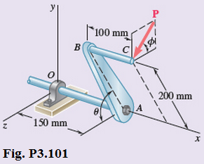
Chapter 3, Problem 101RP
A single force P acts at C in a direction perpendicular to the handle BC of the crank shown. Determine page the moment
Expert Solution & Answer
Want to see the full answer?
Check out a sample textbook solution
Students have asked these similar questions
Q2/ Maria has an online shop where she sells hand made paintings and
cards. She sells the painting for 50 and the card for 20. It takes her 2 hours
to complete 1 painting and 45 minutes to make a single card. She also has
a day job and makes paintings and cards in her free time. She cannot spend
more than 15 hours a week to make paintings and cards. Additionally, she
should make not more than 10 paintings and cards per week.
She makes a profit of 25 on painting and 15 on each card. How many
paintings and cards should she make each week to maximize her profit.
For the beam and loading shown, (a) draw the shear and bending moment diagrams, (b) determine the magnitude and location of the maximum absolute value of the bending momentConsider A = 0please show step by step process, i did something wrong with bending moment diagram( length of beam = 2 + 6 + 2)
CORRECT ANSWER ONLY WITH COMPLETE FBD. PREFERABLY HANDWRITTEN. I WILL UPVOTE
1. The beam shown carries the following loads:Total dead load, wDL = 36 kN/mConcentrated live load, PLL = 240 kNThe beam section is HSS16X12X3/8 with properties:Span, L = 6 mArea, A = 12,100 mm2Moment of inertia about x-axis, Ix = 292 x 106 mm4Fy = 345 MPa
1. Calculate the location of the live load, from the left support, for maximum moment to occur at the fixed support.Answer: 2.536 m2. Calculate the maximum moment. Answer: 439.128 kN-m
Chapter 3 Solutions
Statics and Mechanics of Materials
Ch. 3.1 - A 20-lb force is applied to the control rod AB as...Ch. 3.1 - A 20-lb force is applied to the control rod AB as...Ch. 3.1 - A 300-N force P is applied at point A of the bell...Ch. 3.1 - A 400-N force P is applied at point A of the bell...Ch. 3.1 - A 300-N force is applied at A as shown. Determine...Ch. 3.1 - A 300-N force is applied at A as shown. Determine...Ch. 3.1 - 3.7 and 3.8 The tailgate of a car is supported by...Ch. 3.1 - 3.7 and 3.8 The tailgate of a car is supported by...Ch. 3.1 - 3.9 and 3.10 It is known that the connecting rod...Ch. 3.1 - 3.9 and 3.10 It is known that the connecting rod...
Ch. 3.1 - Rod AB is held in place by the cord AC. Knowing...Ch. 3.1 - Prob. 12PCh. 3.1 - Determine the moment about the origin O of the...Ch. 3.1 - Determine the moment about the origin O of the...Ch. 3.1 - Prob. 15PCh. 3.1 - Prob. 16PCh. 3.1 - Prob. 17PCh. 3.1 - A wooden board AB, which is used as a temporary...Ch. 3.1 - Prob. 19PCh. 3.1 - A small boat hangs from two davits, one of which...Ch. 3.1 - Prob. 21PCh. 3.1 - In Prob. 3.16, determine the perpendicular...Ch. 3.1 - In Prob. 3.16, determine the perpendicular...Ch. 3.1 - In Prob. 3.20, determine the perpendicular...Ch. 3.2 - Given the vectors P=3i-j+2k,Q=4i+5j-3k, and...Ch. 3.2 - Prob. 26PCh. 3.2 - Knowing that the tension in cable AC is 1260 N,...Ch. 3.2 - Knowing that the tension in cable AD is 405 N,...Ch. 3.2 - Three cables are used to support a container as...Ch. 3.2 - Three cables are used to support a container as...Ch. 3.2 - The 20-in. tube AB can slide along a horizontal...Ch. 3.2 - Solve Prob. 3.31 for the position corresponding to...Ch. 3.2 - Prob. 33PCh. 3.2 - Prob. 34PCh. 3.2 - Knowing that the tension in cable AB is 570 N,...Ch. 3.2 - Prob. 36PCh. 3.2 - A farmer uses cables and winch pullers B and E to...Ch. 3.2 - Solve Prob. 3.37 when the tension in cable AB is...Ch. 3.2 - To lift a heavy crate, a man uses a block and...Ch. 3.2 - Prob. 40PCh. 3.2 - Prob. 41PCh. 3.2 - Prob. 42PCh. 3.2 - Prob. 43PCh. 3.2 - A sign erected on uneven ground is guyed by cables...Ch. 3.2 - The frame ACD is hinged at and D and is supported...Ch. 3.2 - In Prob. 3.45, determine the moment about the...Ch. 3.2 - Prob. 47PCh. 3.2 - Prob. 48PCh. 3.3 - Two parallel 60-N forces are applied to a lever as...Ch. 3.3 - A plate in the shape of a parallelogram is acted...Ch. 3.3 - Prob. 51PCh. 3.3 - Prob. 52PCh. 3.3 - Four 112-in. -diameter pegs are attached to a...Ch. 3.3 - Prob. 54PCh. 3.3 - Prob. 55PCh. 3.3 - Prob. 56PCh. 3.3 - Replace the two couples shown with a single...Ch. 3.3 - Prob. 58PCh. 3.3 - Shafts A and B connect the gear box to the wheel...Ch. 3.3 - Prob. 60PCh. 3.3 - Prob. 61PCh. 3.3 - The force P has a magnitude of 250 N and is...Ch. 3.3 - Prob. 63PCh. 3.3 - A 260-lb force is applied at A to the rolled-steel...Ch. 3.3 - Prob. 65PCh. 3.3 - A force and couple act as shown on a square plate...Ch. 3.3 - Prob. 67PCh. 3.3 - Prob. 68PCh. 3.3 - Prob. 69PCh. 3.3 - Replace the 150-N force by an equivalent...Ch. 3.3 - Prob. 71PCh. 3.3 - Prob. 72PCh. 3.4 - A 4-m-long beam is subjected to a variety of...Ch. 3.4 - Prob. 74PCh. 3.4 - Determine the single equivalent force and the...Ch. 3.4 - The weights of two children sitting at ends A and...Ch. 3.4 - Prob. 77PCh. 3.4 - Prob. 78PCh. 3.4 - Four forces act on a 700375 -mm plate as shown....Ch. 3.4 - Prob. 80PCh. 3.4 - Prob. 81PCh. 3.4 - A truss supports the loading shown. Determine the...Ch. 3.4 - A machine component is subjected to the forces and...Ch. 3.4 - Solve Prob. 3.83, assuming that P=60N.Ch. 3.4 - Prob. 85PCh. 3.4 - Prob. 86PCh. 3.4 - Prob. 87PCh. 3.4 - Prob. 88PCh. 3.4 - Prob. 89PCh. 3.4 - Assuming e 600 in Prob. 3.89, replace the two...Ch. 3.4 - A blade held in a brace is used to tighten a screw...Ch. 3.4 - Prob. 92PCh. 3.4 - Four signs are mounted on a frame spanning a...Ch. 3.4 - Prob. 94PCh. 3.4 - Prob. 95PCh. 3.4 - Three children are standing on a 55-m raft. The...Ch. 3 - For the shift lever shown, determine the magnitude...Ch. 3 - Consider the volleyball net shown. Determine the...Ch. 3 - A crane is oriented so that the end of the 25-m...Ch. 3 - The 25-m crane boom AO lies in the yz plane....Ch. 3 - A single force P acts at C in a direction...Ch. 3 - While tapping a hole, a machinist applies the...Ch. 3 - A 500-N force is applied to a bent plate as shown....Ch. 3 - Prob. 104RPCh. 3 - Prob. 105RPCh. 3 - Prob. 106RPCh. 3 - Prob. 107RPCh. 3 - A regular tetrahedron has six edges of length a. A...
Knowledge Booster


Learn more about
Need a deep-dive on the concept behind this application? Look no further. Learn more about this topic, mechanical-engineering and related others by exploring similar questions and additional content below.Similar questions
- CORRECT ANSWER AND COMPLETE FBD ONLY. I PREFER HANDWRITTEN BUT ITS OKAY IF NOT. I WILL UPVOTE 2. The space truss shown is supported by ball-and-socket joints at A, B and C. Factored loads P1 and P2 areacting on joints D and E, respectively, towards the negative y-direction. 1. Calculate the stress of member CE, indicate tension or compression. Answer: 23.61 MPa Tension2. Calculate the stress of member AD, indicate tension or compression. Answer: 21.01 MPa Compression3. Calculate the stress of member CD, indicate tension or compression. Answer: 11.03 MPa Tensionarrow_forwardCORRECT ANSWER AND COMPLETE FBD ONLY. I PREFER HANDWRITTEN BUT ITS OKAY IF NOT. I WILL UPVOTE 3. The frame has pin supports at A and E, subject to a wind load. Treat joint C to be an internal hinge. Given:Dimensions, H1 = 3.0 m; H2 = 4.5 m; L = 10.0 mWind loads, wWL (AB) = 4.8 kN/m; wWL (BC) = 3.9 kN/m; wWL (CD) = 1.5 kN/m; wWL (DE) = 1.2 kN/mMembers are made of A36 steel Wide Flange Section with the following properties:Area, A = 64000 mm2Depth, d = 762 mmFlange width, bf = 371 mmThickness of web, tw = 32 mmThickness of flange, tf = 57.9 mmMoment of inertia about x-axis, Ix = 6080 x 106 mm4The wide flange is oriented so that the bending is about the x-axis1. Calculate the stress in member AB, due to the axial load it carries, indicate if tension or compression.Answer: 0.0476 MPa Tension2. Calculate the stress in member DE, due to the axial load it carries, indicate if tension or compression.Answer: 0.2351 MPa Compression3. Calculate the maximum bending stress at B. Answer: 4.282 MPaarrow_forward32 mm 32 mm b' c' C 32 mm 32 mm b PROBLEM 6.41 a The extruded beam shown has a uniform wall thickness of 3 mm. Knowing that the vertical shear in the beam is 9 kN, determine the shearing stress at each of the five points indicated.arrow_forward
- In a structural reliability problem, the resistance (capacity) R and load effect (demand) S random variables associated with a failure mode of the structure of interest are normally distributed and statistically independent with the following probability distribution parameters (or statistics) in consistent units: MR = 12, σR = 3 μs = 5, σs = 2 (a) Determine the exact probability of failure pF ·arrow_forwardThe resistance R and load effect S for a given failure mode are statistically independent random variables with marginal PDF's 1 fR (r) = 0≤r≤100 100' fs(s)=0.05e-0.05s (a) Determine the probability of failure by computing the probability content of the failure domain defined as {rarrow_forwardPlease solve this problem as soon as possible My ID# 016948724arrow_forwardThe gears shown in the figure have a diametral pitch of 2 teeth per inch and a 20° pressure angle. The pinion rotates at 1800 rev/min clockwise and transmits 200 hp through the idler pair to gear 5 on shaft c. What forces do gears 3 and 4 transmit to the idler shaft? TS I y 18T 32T This a 12 x 18T C 48T 5arrow_forwardQuestion 1. Draw 3 teeth for the following pinion and gear respectively. The teeth should be drawn near the pressure line so that the teeth from the pinion should mesh those of the gear. Drawing scale (1:1). Either a precise hand drawing or CAD drawing is acceptable. Draw all the trajectories of the involute lines and the circles. Specification: 18tooth pinion and 30tooth gear. Diameter pitch=P=6 teeth /inch. Pressure angle:20°, 1/P for addendum (a) and 1.25/P for dedendum (b). For fillet, c=b-a.arrow_forward5. The figure shows a gear train. There is no friction at the bearings except for the gear tooth forces. The material of the milled gears is steel having a Brinell hardness of 170. The input shaft speed (n2) is 800 rpm. The face width and the contact angle for all gears are 1 in and 20° respectively. In this gear set, the endurance limit (Se) is 15 kpsi and nd (design factor) is 2. (a) Find the revolution speed of gear 5. (b) Determine whether each gear satisfies the design factor of 2.0 for bending fatigue. (c) Determine whether each gear satisfies the design factor of 2.0 for surface fatigue (contact stress). (d) According to the computation results of the questions (b) and (c), explain the possible failure mechanisms for each gear. N4=28 800rpm N₁=43 N5=34 N₂=14 P(diameteral pitch)=8 for all gears Coupled to 2.5hp motorarrow_forward1. The rotating steel shaft is simply supported by bearings at points of B and C, and is driven by a spur gear at D, which has a 6-in pitch diameter. The force F from the drive gear acts at a pressure angle of 20°. The shaft transmits a torque to point A of TA =3000 lbĘ in. The shaft is machined from steel with Sy=60kpsi and Sut=80 kpsi. (1) Draw a shear force diagram and a bending moment diagram by F. According to your analysis, where is the point of interest to evaluate the safety factor among A, B, C, and D? Describe the reason. (Hint: To find F, the torque Tд is generated by the tangential force of F (i.e. Ftangential-Fcos20°) When n=2.5, K=1.8, and K₁ =1.3, determine the diameter of the shaft based on (2) static analysis using DE theory (note that fatigue stress concentration factors need to be used for this question because the loading condition is fatigue) and (3) a fatigue analysis using modified Goodman. Note) A standard diameter is not required for the questions. 10 in Darrow_forward3 N2=28 P(diametral pitch)=8 for all gears Coupled to 25 hp motor N3=34 Full depth spur gears with pressure angle=20° N₂=2000 rpm (1) Compute the circular pitch, the center-to-center distance, and base circle radii. (2) Draw the free body diagram of gear 3 and show all the forces and the torque. (3) In mounting gears, the center-to-center distance was reduced by 0.1 inch. Calculate the new values of center-to-center distance, pressure angle, base circle radii, and pitch circle diameters. (4)What is the new tangential and radial forces for gear 3? (5) Under the new center to center distance, is the contact ratio (mc) increasing or decreasing?arrow_forward2. A flat belt drive consists of two 4-ft diameter cast-iron pulleys spaced 16 ft apart. A power of 60 hp is transmitted by a pulley whose speed is 380 rev/min. Use a service factor (Ks) pf 1.1 and a design factor 1.0. The width of the polyamide A-3 belt is 6 in. Use CD=1. Answer the following questions. (1) What is the total length of the belt according to the given geometry? (2) Find the centrifugal force (Fc) applied to the belt. (3) What is the transmitted torque through the pulley system given 60hp? (4) Using the allowable tension, find the force (F₁) on the tight side. What is the tension at the loose side (F2) and the initial tension (F.)? (5) Using the forces, estimate the developed friction coefficient (f) (6) Based on the forces and the given rotational speed, rate the pulley set. In other words, what is the horse power that can be transmitted by the pulley system? (7) To reduce the applied tension on the tight side, the friction coefficient is increased to 0.75. Find out the…arrow_forwardarrow_back_iosSEE MORE QUESTIONSarrow_forward_ios
Recommended textbooks for you
 International Edition---engineering Mechanics: St...Mechanical EngineeringISBN:9781305501607Author:Andrew Pytel And Jaan KiusalaasPublisher:CENGAGE L
International Edition---engineering Mechanics: St...
Mechanical Engineering
ISBN:9781305501607
Author:Andrew Pytel And Jaan Kiusalaas
Publisher:CENGAGE L
How to balance a see saw using moments example problem; Author: Engineer4Free;https://www.youtube.com/watch?v=d7tX37j-iHU;License: Standard Youtube License