
Physics for Scientists and Engineers
10th Edition
ISBN: 9781337553278
Author: Raymond A. Serway, John W. Jewett
Publisher: Cengage Learning
expand_more
expand_more
format_list_bulleted
Videos
Textbook Question
Chapter 32, Problem 5P
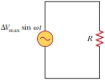
In the AC circuit shown in Figure P32.3, R = 70.0 Ω and the output voltage of the AC source is ΔVmax sin ωt. (a) If ΔVR = 0.250 ΔVmax for the first time at t = 0.0100 s, what is the angular frequency of the source? (b) What is the next value of t for which ΔVR = 0.250 ΔVmax?
Figure P32.6 Problem 3 and 5.
Expert Solution & Answer
Want to see the full answer?
Check out a sample textbook solution
Students have asked these similar questions
4.) The diagram shows the electric field lines of a positively charged conducting sphere of
radius R and charge Q.
A
B
Points A and B are located on the same field line.
A proton is placed at A and released from rest. The magnitude of the work done by the electric field in
moving the proton from A to B is 1.7×10⁻¹⁶ J. Point A is at a distance of 5.0×10⁻²m from the centre of
the sphere. Point B is at a distance of 1.0×10⁻¹ m from the centre of the sphere.
(a) Explain why the electric potential decreases from A to B. [2]
(b) Draw, on the axes, the variation of electric potential V with distance r from the centre of the
sphere.
R
[2]
(c(i)) Calculate the electric potential difference between points A and B. [1]
(c(ii)) Determine the charge Q of the sphere. [2]
(d) The concept of potential is also used in the context of gravitational fields. Suggest why scientists
developed a common terminology to describe different types of fields. [1]
3.) The graph shows how current I varies with potential difference V across a component X.
904
80-
70-
60-
50-
I/MA
40-
30-
20-
10-
0+
0
0.5
1.0 1.5 2.0 2.5 3.0 3.5 4.0 4.5 5.0
VIV
Component X and a cell of negligible internal resistance are placed in a circuit.
A variable resistor R is connected in series with component X. The ammeter reads 20mA.
4.0V
4.0V
Component X and the cell are now placed in a potential divider circuit.
(a) Outline why component X is considered non-ohmic. [1]
(b(i)) Determine the resistance of the variable resistor. [3]
(b(ii)) Calculate the power dissipated in the circuit. [1]
(c(i)) State the range of current that the ammeter can measure as the slider S of the potential divider
is moved from Q to P. [1]
(c(ii)) Describe, by reference to your answer for (c)(i), the advantage of the potential divider
arrangement over the arrangement in (b).
1.) Two long parallel current-carrying wires P and Q are separated by 0.10 m. The current in wire P is 5.0 A.
The magnetic force on a length of 0.50 m of wire P due to the current in wire Q is 2.0 × 10-s N.
(a) State and explain the magnitude of the force on a length of 0.50 m of wire Q due to the current in P. [2]
(b) Calculate the current in wire Q. [2]
(c) Another current-carrying wire R is placed parallel to wires P and Q and halfway between them as shown.
wire P
wire R
wire Q
0.05 m
0.05 m
The net magnetic force on wire Q is now zero.
(c.i) State the direction of the current in R, relative to the current in P.[1]
(c.ii) Deduce the current in R. [2]
Chapter 32 Solutions
Physics for Scientists and Engineers
Ch. 32.2 - Consider the voltage phasor in Figure 32.4, shown...Ch. 32.3 - Consider the AC circuit in Figure 32.8. The...Ch. 32.4 - Consider the AC circuit in Figure 32.11. The...Ch. 32.4 - Consider the AC circuit in Figure 32.12. The...Ch. 32.5 - Label each part of Figure 32.16, (a), (b), and...Ch. 32.6 - An AC source drives an RLC circuit with a fixed...Ch. 32.7 - What is the impedance of a series RLC circuit at...Ch. 32 - (a) What is the resistance of a lightbulb that...Ch. 32 - A certain lightbulb is rated at 60.0 W when...Ch. 32 - The current in the circuit shown in Figure P32.3...
Ch. 32 - Figure P32.4 shows three lightbulbs connected to a...Ch. 32 - In the AC circuit shown in Figure P32.3, R = 70.0 ...Ch. 32 - In a purely inductive AC circuit as shown in...Ch. 32 - Prob. 7PCh. 32 - A 20.0-mH inductor is connected to a North...Ch. 32 - An AC source has an output rms voltage of 78.0 V...Ch. 32 - Review. Determine the maximum magnetic flux...Ch. 32 - A 1.00-mF capacitor is connected to a North...Ch. 32 - An AC source with an output rms voltage of 86.0 V...Ch. 32 - What is the maximum current in a 2.20-F capacitor...Ch. 32 - A capacitor C is connected to a power supply that...Ch. 32 - In addition to phasor diagrams showing voltages...Ch. 32 - An AC source with Vmax = 150 V and f = 50.0 Hz is...Ch. 32 - You are working in a factory and have been tasked...Ch. 32 - Prob. 18PCh. 32 - An RLC circuit consists of a 150- resistor, a...Ch. 32 - A 60.0-ft resistor is connected in series with a...Ch. 32 - A series RLC circuit has a resistance of 45.0 and...Ch. 32 - Prob. 22PCh. 32 - A series RLC circuit has a resistance of 22.0 and...Ch. 32 - An AC voltage of the form v = 90.0 sin 350t, where...Ch. 32 - The LC circuit of a radar transmitter oscillates...Ch. 32 - A series RLC circuit has components with the...Ch. 32 - You wish to build a series RLC circuit for a...Ch. 32 - A 10.0- resistor, 10.0-mH inductor, and 100-F...Ch. 32 - A resistor R, inductor L, and capacitor C are...Ch. 32 - The primary coil of a transformer has N1 = 350...Ch. 32 - A person is working near the secondary of a...Ch. 32 - A transmission line that has a resistance per unit...Ch. 32 - Prob. 33APCh. 32 - A 400- resistor, an inductor, and a capacitor are...Ch. 32 - Energy is to be transmitted over a pair of copper...Ch. 32 - Energy is to be transmitted over a pair of copper...Ch. 32 - A transformer may be used to provide maximum power...Ch. 32 - Show that the rms value for the sawtooth voltage...Ch. 32 - Marie Cornu, a physicist at the Polytechnic...Ch. 32 - A series RLC circuit has resonance angular...Ch. 32 - Review. One insulated conductor from a household...Ch. 32 - (a) Sketch a graph of the phase angle for an RLC...Ch. 32 - Prob. 43APCh. 32 - Review. In the circuit shown in Figure P32.44,...Ch. 32 - You have decided to build your own speaker system...Ch. 32 - A series RLC circuit is operating at 2.00 103 Hz....Ch. 32 - You are trying to become a member of the Physics...Ch. 32 - A series RLC circuit in which R = l.00 , L = 1.00...Ch. 32 - The resistor in Figure P32.49 represents the...Ch. 32 - An 80.0- resistor and a 200-mH inductor are...Ch. 32 - Prob. 51CP
Knowledge Booster


Learn more about
Need a deep-dive on the concept behind this application? Look no further. Learn more about this topic, physics and related others by exploring similar questions and additional content below.Similar questions
- 2.) A 50.0 resistor is connected to a cell of emf 3.00 V. The voltmeter and the ammeter in the circuit are ideal. V A 50.00 (a) The current in the ammeter is 59.0 mA. Calculate the internal resistance of the cell. The circuit is changed by connecting another resistor R in parallel to the 50.0 resistor. V A 50.00 R (b) Explain the effect of this change on R is made of a resistive wire of uniform cross-sectional area 3.1 × 10⁻⁸ m², resistivity 4.9 × 10-70m and length L. The resistance of R is given by the equation R = KL where k is a constant. (b.i) the reading of the ammeter. [2] (b.ii) the reading of the voltmeter. [2] (c) Calculate k. State an appropriate unit for your answer. [3] [2]arrow_forwardNo chatgpt pls will upvotearrow_forwardNo chatgpt pls will upvotearrow_forward
- A rod 12.0 cm long is uniformly charged and has a total charge of -20.0 μc. Determine the magnitude and direction of the electric field along the axis of the rod at a point 32.0 cm from its center. 361000 ☑ magnitude What is the general expression for the electric field along the axis of a uniform rod? N/C direction toward the rodarrow_forwardA certain brand of freezer is advertised to use 730 kW h of energy per year. Part A Assuming the freezer operates for 5 hours each day, how much power does it require while operating? Express your answer in watts. ΜΕ ΑΣΦ ? P Submit Request Answer Part B W If the freezer keeps its interior at a temperature of -6.0° C in a 20.0° C room, what is its theoretical maximum performance coefficient? Enter your answer numerically. K = ΜΕ ΑΣΦ Submit Request Answer Part C What is the theoretical maximum amount of ice this freezer could make in an hour, starting with water at 20.0°C? Express your answer in kilograms. m = Ο ΑΣΦ kgarrow_forwardDescribe the development of rational choice theory in sociology. Please includearrow_forward
- A-E pleasearrow_forwardA 11.8 L gas tank containing 3.90 moles of ideal He gas at 26.0°C is placed inside a completely evacuated insulated bell jar of volume 39.0 L .A small hole in the tank allows the He to leak out into the jar until the gas reaches a final equilibrium state with no more leakage. Part A What is the change in entropy of this system due to the leaking of the gas? ■ ΜΕ ΑΣΦ AS = ? J/K Submit Request Answer Part B Is the process reversible or irreversible?arrow_forwardA-E pleasearrow_forward
- Three moles of an ideal gas undergo a reversible isothermal compression at 20.0° C. During this compression, 1900 J of work is done on the gas. For related problem-solving tips and strategies, you may want to view a Video Tutor Solution of Entropy change in a free expansion. Part A What is the change of entropy of the gas? ΤΕ ΑΣΦ AS = Submit Request Answer J/Karrow_forward5.97 Block A, with weight 3w, slides down an inclined plane S of slope angle 36.9° at a constant speed while plank B, with weight w, rests on top of A. The plank is attached by a cord to the wall (Fig. P5.97). (a) Draw a diagram of all the forces acting on block A. (b) If the coefficient of kinetic friction is the same between A and B and between S and A, determine its value. Figure P5.97 B A S 36.9°arrow_forwardPlease take your time and solve each part correctly please. Thank you!!arrow_forward
arrow_back_ios
SEE MORE QUESTIONS
arrow_forward_ios
Recommended textbooks for you
 Physics for Scientists and EngineersPhysicsISBN:9781337553278Author:Raymond A. Serway, John W. JewettPublisher:Cengage Learning
 Physics for Scientists and Engineers with Modern ...PhysicsISBN:9781337553292Author:Raymond A. Serway, John W. JewettPublisher:Cengage Learning
 Physics for Scientists and Engineers: Foundations...PhysicsISBN:9781133939146Author:Katz, Debora M.Publisher:Cengage Learning
 College PhysicsPhysicsISBN:9781305952300Author:Raymond A. Serway, Chris VuillePublisher:Cengage Learning
 Physics for Scientists and Engineers, Technology ...PhysicsISBN:9781305116399Author:Raymond A. Serway, John W. JewettPublisher:Cengage Learning
Physics for Scientists and Engineers
Physics
ISBN:9781337553278
Author:Raymond A. Serway, John W. Jewett
Publisher:Cengage Learning
Physics for Scientists and Engineers with Modern ...
Physics
ISBN:9781337553292
Author:Raymond A. Serway, John W. Jewett
Publisher:Cengage Learning
Physics for Scientists and Engineers: Foundations...
Physics
ISBN:9781133939146
Author:Katz, Debora M.
Publisher:Cengage Learning
College Physics
Physics
ISBN:9781305952300
Author:Raymond A. Serway, Chris Vuille
Publisher:Cengage Learning
Physics for Scientists and Engineers, Technology ...
Physics
ISBN:9781305116399
Author:Raymond A. Serway, John W. Jewett
Publisher:Cengage Learning
Introduction To Alternating Current; Author: Tutorials Point (India) Ltd;https://www.youtube.com/watch?v=0m142qAZZpE;License: Standard YouTube License, CC-BY