You are trying to become a member of the Physics Olympics team. Your physics professor is training you and some other students by having you compete with each other to solve problems as accurately and quickly as you can. During one session, he springs the RLC circuit shown in Figure P32.47 (page 872) on you. Figure P32.47a shows the circuit with a battery as the energy source. The battery has an emf
- If only switch SL is closed, and switches SC and SR are open, and then switch S is thrown to position b, the time constant of the circuit is τ1 = 0.200 ms. Switch S is returned to position a for a long time.
Figure P32.47
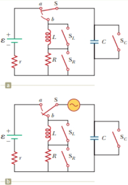
- If only switch SC is closed, and switches SL and SR are open, and then switch S is thrown to position b, the time constant of the circuit is τ2 = 0.050 0 ms. Switch S is returned to position a for a long time.
In Figure P32.47b, an AC source with a variable frequency has been added to the same circuit, and switch S is thrown to position b. Switches SC, SL, and SR are all open. At what angular frequency ω should the AC source be set so that the circuit exhibits resonance? Quick! Get to work!
Want to see the full answer?
Check out a sample textbook solutionChapter 32 Solutions
Physics for Scientists and Engineers
- In Figure P29.81, N real batteries, each with an emf and internal resistance r, are connected in a closed ring. A resistor R can be connected across any two points of this ring, causing there to be n real batteries in one branch and N n resistors in the other branch. Find an expression for the current through the resistor R in this case.arrow_forwardThe circuit shown in Figure P28.78 is set up in the laboratory to measure an unknown capacitance C in series with a resistance R = 10.0 M powered by a battery whose emf is 6.19 V. The data given in the table are the measured voltages across the capacitor as a function of lime, where t = 0 represents the instant at which the switch is thrown to position b. (a) Construct a graph of In (/v) versus I and perform a linear least-squares fit to the data, (b) From the slope of your graph, obtain a value for the time constant of the circuit and a value for the capacitance. v(V) t(s) In (/v) 6.19 0 5.56 4.87 4.93 11.1 4.34 19.4 3.72 30.8 3.09 46.6 2.47 67.3 1.83 102.2arrow_forwardFigure P29.84 shows a circuit that consists of two identical emf devices. If R1 = R2 = R and the switch is closed, find an expression (in terms of R and ) for the current I that is in the branch from point a to b.arrow_forward
- In the circuit of Figure P27.25, the switch S has been open for a long time. It is then suddenly closed. Determine the time constant (a) before the switch is closed and (b) after the switch is closed. (c) Let the switch be closed at t = 0. Determine the current in the switch as a function of time. Figure P27.25 Problems 25 and 26.arrow_forwardThree resistors with resistances R1 = R/2 and R2 = R3 = R are connected as shown, and a potential difference of 225 V is applied across terminals a and b (Fig. P29.49). a. If the resistor R1 dissipates 75.0 W of power, what is the value of R? b. What is the total power supplied to the circuit by the emf? c. What is the potential difference across each of the three resistors?arrow_forwardTwo circuits made up of identical ideal emf devices ( = 1.67 V) and resistors (R = 35.9 ) are shown in Figure P29.8. What is the potential difference Vb Va a. for circuit 1 and b. for circuit 2? What is the current in the resistor c. in circuit 1 and d. in circuit 2?arrow_forward
- Figure P29.60 shows a simple RC circuit with a 2.50-F capacitor, a 3.50-M resistor, a 9.00-V emf, and a switch. What are a. the charge on the capacitor, b. the current in the resistor, c. the rate at which the capacitor is storing energy, and d. the rate at which the battery is delivering energy exactly 7.50 s alter the switch is closed?arrow_forwardIn the RC circuit shown in Figure P29.78, an ideal battery with emf and internal resistance r is connected to capacitor C. The switch S is initially open and the capacitor is uncharged. At t = 0, the switch is closed. a. Determine the charge q on the capacitor at time t. b. Find the current in the branch be at time t. What is the current as t goes to infinity?arrow_forwardWhat is the equivalent resistance between points a and b of the six resistors shown in Figure P29.70? FIGURE P29.70arrow_forward
- At time t = 0, an RC circuit consists of a 12.0-V emf device, a 60.0- resistor, and a 150.0-F capacitor that is fully charged. The switch is thrown so that the capacitor begins to discharge. a. What is the time constant t of this circuit? b. How much charge is stored by the capacitor at t = 0.5, 2, and 4?arrow_forwardEach resistor shown in Figure P29.36 has a resistance of 100.0 . An ideal emf device (120.0 V) is connected to points a and b via two leads (not shown in the figure). Find the current that flows through the emf device.arrow_forwardAn ideal emf device is connected to a set of resistors as shown in Figure P29.66. Find an expression for the current through the resistor R3 in terms of the emf and the resistances.arrow_forward
- Physics for Scientists and EngineersPhysicsISBN:9781337553278Author:Raymond A. Serway, John W. JewettPublisher:Cengage LearningPhysics for Scientists and Engineers with Modern ...PhysicsISBN:9781337553292Author:Raymond A. Serway, John W. JewettPublisher:Cengage LearningPrinciples of Physics: A Calculus-Based TextPhysicsISBN:9781133104261Author:Raymond A. Serway, John W. JewettPublisher:Cengage Learning
- Physics for Scientists and Engineers, Technology ...PhysicsISBN:9781305116399Author:Raymond A. Serway, John W. JewettPublisher:Cengage LearningCollege PhysicsPhysicsISBN:9781305952300Author:Raymond A. Serway, Chris VuillePublisher:Cengage LearningPhysics for Scientists and Engineers: Foundations...PhysicsISBN:9781133939146Author:Katz, Debora M.Publisher:Cengage Learning