
Precision Machining Technology
3rd Edition
ISBN: 9781337795302
Author: Peter, Hoffman.
Publisher: Cengage Learning,
expand_more
expand_more
format_list_bulleted
Concept explainers
Question
Chapter 3.1, Problem 3RQ
To determine
The views shown in the sketch.
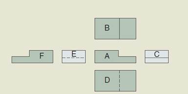
Figure (1)
Expert Solution & Answer

Trending nowThis is a popular solution!

Students have asked these similar questions
practice problems want detailed break down
6.105. Determine force P on the cable if the spring is compressed 0.025 m when the mechanism is in the
position shown. The spring has a stiffness of k = 6 kN/m.
E
P
150 mm
D
T
30°
200 mm
200 mm
200 mm
B
800 mm
6.71. Determine the reactions at the supports A, C, and E of the compound beam.
3 kN/m
12 kN
A
B
CD
E
-3 m 4 m
6 m
3 m
2 m
Chapter 3 Solutions
Precision Machining Technology
Ch. 3.1 - Information such as tolerances and scale can be...Ch. 3.1 - What view of a drawing usually shows the most...Ch. 3.1 - Prob. 3RQCh. 3.1 - The line type used to show edges of an object that...Ch. 3.1 - What line type is used to show edges of an object...Ch. 3.1 - What two line types work together to show sizes on...Ch. 3.1 - Identify the line types labeled in the print...Ch. 3.1 - Define and briefly describe the following...Ch. 3.1 - A dimension listed on an engineering drawing is...Ch. 3.1 - List and briefly describe the three types of...
Ch. 3.1 - Briefly describe the difference between a...Ch. 3.1 - The relationship between sizes of mating parts is...Ch. 3.1 - What does GDT stand for?Ch. 3.1 - A plane used as a reference for dimensions is...Ch. 3.1 - A GDT symbol and the amount of tolerance are shown...Ch. 3.1 - What are the five categories of symbols used in...Ch. 3.1 - What is a feature of size?Ch. 3.1 - Briefly explain the benefit of a position...Ch. 3.2 - Prob. 1RQCh. 3.2 - What is the purpose of layout fluid (dye)?Ch. 3.2 - Prob. 3RQCh. 3.2 - Briefly define a scriber and its use.Ch. 3.2 - What two angles can be laid out with the...Ch. 3.2 - What two tasks can a divider be used to perform?Ch. 3.2 - What safety precautions should be observed when...Ch. 3.2 - What would the divider setting be to scribe a...Ch. 3.2 - What would the divider setting be to scribe an arc...Ch. 3.2 - Prob. 10RQCh. 3.2 - Prob. 11RQCh. 3.2 - Briefly describe the use of a surface gage.Ch. 3.3 - What are three safety rules to observe when using...Ch. 3.3 - List three types of screwdriver tips.Ch. 3.3 - What is the advantage of using slip joint pliers?Ch. 3.3 - What is an advantage of using locking pliers?Ch. 3.3 - What are two uses for a ball peen hammer?Ch. 3.3 - What is the advantage of a soft face hammer?Ch. 3.3 - In what situation would a box-end wrench be chosen...Ch. 3.3 - List two precautions to observe when using...Ch. 3.3 - What is one method of preventing damage to work...Ch. 3.3 - List three safety precautions to be observed when...Ch. 3.3 - In which direction should hacksaw blade teeth...Ch. 3.3 - List two safety precautions that should be...Ch. 3.3 - Will a single-cut or a double-cut file remove...Ch. 3.3 - Will a single-cut or a double-cut file produce a...Ch. 3.3 - ___________ and _________ are two common filing...Ch. 3.3 - What tool is used to clean a file?Ch. 3.3 - What are the two forms of abrasives used in...Ch. 3.4 - Sawing machines can be divided into roughly four...Ch. 3.4 - The vertical band saw is particularly useful, as...Ch. 3.4 - The horizontal band saw is ideal for cutting...Ch. 3.4 - Cutting action on the power hacksaw is very...Ch. 3.4 - List three safety precautions to observe when...Ch. 3.4 - Briefly describe the process to prepare for...Ch. 3.4 - List three safety precautions to observe when...Ch. 3.4 - What type of band saw blade has HSS teeth welded...Ch. 3.4 - How many saw teeth should be engaged in the...Ch. 3.4 - Name the three different types of tooth patterns.Ch. 3.4 - What are the three types of tooth set and why is...Ch. 3.4 - The slot created in a workpiece by the saw blade...Ch. 3.4 - Explain how to use a push stick.Ch. 3.4 - Saws should be ____________ _____________ when a...Ch. 3.4 - Saw guides should be mounted ________ above the...Ch. 3.4 - Why must a band saw blade be annealed after...Ch. 3.4 - Why does a band saw blade need to be ground after...Ch. 3.4 - Clearance between the vertical band saw guides and...Ch. 3.4 - Band saw cutting speeds are given in _________.Ch. 3.5 - What is the main benefit of offhand abrasive...Ch. 3.5 - What type of metals should not be ground on a...Ch. 3.5 - Which wheel is finer, a 60 grit or a 36 grit?Ch. 3.5 - If a grinder runs at 3400 RPM and you have a wheel...Ch. 3.5 - How is a ring test performed?Ch. 3.5 - Why is it necessary to have blotters on both sides...Ch. 3.5 - The maximum distance that a spark breaker and tool...Ch. 3.5 - When should a grinding wheel be dressed?Ch. 3.5 - Where should you stand when using a grinder?Ch. 3.6 - Define drilling.Ch. 3.6 - What factors might determine when a hole must be...Ch. 3.6 - Prob. 3RQCh. 3.6 - Explain the purpose of a counterbore.Ch. 3.6 - What is the purpose of the pilot on a counterbore?Ch. 3.6 - What should be done as a drill nears the...Ch. 3.6 - Define thread as it relates to benchwork.Ch. 3.6 - Explain the major diameter of a thread.Ch. 3.6 - What is the TPI of a -20 thread?Ch. 3.6 - Name two types of tap wrenches.Ch. 3.6 - A 3/8-16 threaded hole needs to be tapped deeper....
Knowledge Booster


Learn more about
Need a deep-dive on the concept behind this application? Look no further. Learn more about this topic, mechanical-engineering and related others by exploring similar questions and additional content below.Similar questions
- A countershaft carrying two V-belt pullets is shown in the figure. Pulley A receives power from a motor through a belt with the belt tensions shown. The power is transmitted through the shaft and delivered to the belt on pulley B. Assume the belt tension on the loose side (T1) at B is 30% of the tension on the tight side (T2). (a) Determine the tension (i.e., T₂ and T₁) in the belt on pulley B, assuming the shaft is running at a constant speed. (b) Find the magnitudes of the bearing reaction forces, assuming the bearings act as simple supports. (c) Draw shear-force and bending moment diagrams for the shaft (in XZ and XY plane if needed). (d) Calculate the maximum moments at points A and B respectively and find the point of maximum bending moment (A or B). (e) Find maximum stresses (tensile, compressive, and shear stresses) at the identified point of maximum moment (hint: principal and max shear stresses) 8 dia. 9 400lbf 50lbf 45° 1.5 dia. T₂ B Units in inches T₁ 10 dia.arrow_forwardThe cantilevered bar in the figure is made from a ductile material and is statically loaded with F,, = 200 lbf and Fx = F₂ = 0. Analyze the stress situation in rod AB by obtaining the following information. Note that the stress concentration factors are neglected in the following questions (Kt and Kts=1). (a) Determine the precise location of the critical stress element. (b) Sketch the critical stress element and determine magnitudes and direction for all stresses acting on it. (Transverse shear may only be neglected if you can justify this decision.) (c) For the critical stress element, determine the principal stresses and maximum shear stress. 6 in 1-in dia. B +1- in in 2 in 5 inarrow_forwardA laminated thick-walled hydraulic cylinder was fabricated by shrink-fitting jacket having an outside diameter of 300mm onto a SS 304 steel tube having an inside diameter of 100mm and an outside diameter of 200mm as shown in the figure. The interference (8) was 0.15mm. When the Young's modulus for both SS304 and 1020 steel is the same as 200GPa, and the Poisson's ratio is also the same as 0.3 for both materials, find the followings. Initially 100 mm Initially 200 mm Initially 300 mm SS 304 1020 steel (a) P; (interfacial contact stress) (b) The maximum stresses (σ, and σ+) in the laminated steel cylinder resulting from the shrink fit.arrow_forward
- Auto Controls Design a proportional derivitivecontroller for a plant orsystemthat satisfies the following specifications : 1. is steady-state error is less than 2 % for a ramp input. 2.) Damping ratio (zeta) is greater than 0.7have determined the 3. Once youvalue of kp and kd, then plotthe response of the compensated(with controller) and uncompensated( without the controller, only the plantsystem using MATLAB.arrow_forwardAuto Controls (a) Refer to the above figure .What kind of controller is it ? (b) simplify the block diagramto derive the closed loop transfer function of the system. (C) What are the assumptions thatare needed to make to findthe controller gain ? What arethe value of Kp , Ti and Td ?arrow_forwardAuto Controls Design a PID controller for thefollowing system so that the modified system satisfies the followingspecifications : 1. settling time ,ts = 1.96 s and % Overshoot Mp = 70.7 % Assume a non-dominant pole at s = -15 to solve the problem The plot the compensated andThen plot the uncompensated system in MATLAB. what can you see from the plot ? what is your observation ?arrow_forward
- Fourth year Monthly exam\3 2024-2025 Power plant Time: 1 Hr Q1. A gas turbine power plant operates on a modified Brayton cycle consisting of two-stage compression with intercooling to the initial temperature between stages, two-stage expansion with reheating to the maximum cycle temperature, and two regenerative heat exchangers. The following data is given: Inlet air temperature: 300 K Maximum cycle temperature: 1400 K Pressure ratio across each compressor stage: 4 Pressure ratio across each turbine stage: 4 Isentropic efficiency of compressors and turbines: 85% Effectiveness of each regenerator: 80% a) Draw a schematic and T-s diagram of the cycle. b) Determine the thermal efficiency of the cycle. c) Calculate the net specific work output (in kJ/kg). d) Discuss the impact of regenerators on the cycle performance. Examiner Prof. Dr. Adil Al-Kumaitarrow_forwardAuto Controls The figure is a schematic diagram of an aircraft elevator control system. The input to the systemin the deflection angle of the control lever , and the output is the elevator angle phi.show that for each angle theta of the control lever ,there is a corresponding elevator angle phi. Then find Y(s)/theta(s) and simplify the resulting transfer function . Also note from the diagram that y and phi is relatedarrow_forwardLiquid hexane flows through a counter flow heat exchanger at 5 m3/h as shown in Figure E5.5.The hexane enters the heat exchanger at 90°C. Water, flowing at 5 m3/h, is used to cool the hexane.The water enters the heat exchanger at 15°C. The UA product of the heat exchanger is found to be2.7 kW/K. Determine the outlet temperatures of the hot and cold fluids and the heat transfer ratebetween them using LMTD method.arrow_forward
- Determine the fluid outlet temperatures and the heat transfer rate for the counter flow heatexchanger described in Problem 3 using the ε-NTU model. Assume that the properties can beevaluated at the given fluid inlet temperatures.arrow_forwardSection View - practice Homework 0.5000 3.0000 2,0000 1.0000arrow_forwardDrawing the section view for the following multiview drawing AutoCAD you see the section pratice I need to show how to autocadarrow_forward
arrow_back_ios
SEE MORE QUESTIONS
arrow_forward_ios
Recommended textbooks for you
 Welding: Principles and Applications (MindTap Cou...Mechanical EngineeringISBN:9781305494695Author:Larry JeffusPublisher:Cengage Learning
Welding: Principles and Applications (MindTap Cou...
Mechanical Engineering
ISBN:9781305494695
Author:Larry Jeffus
Publisher:Cengage Learning