
Videos
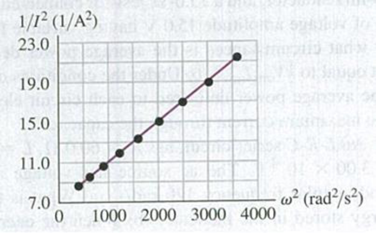
DATA A coworker of yours was making measurements of a large solenoid that is connected to an ac voltage source. Unfortunately, she left for vacation before she completed the analysis, and your boss has asked you to finish it. You are given a graph of l/I2 versus ω2 (Fig. P31.64), where I is the current in the circuit and ω is the angular frequency of the source. A note attached to the graph says that the voltage amplitude of the source was kept constant at 12.0 V. Calculate the resistance and inductance of the solenoid.
Figure P31.64
Want to see the full answer?
Check out a sample textbook solution
Chapter 31 Solutions
University Physics (14th Edition)
Additional Science Textbook Solutions
The Cosmic Perspective
Conceptual Integrated Science
Sears And Zemansky's University Physics With Modern Physics
Tutorials in Introductory Physics
Modern Physics
Physics for Scientists and Engineers: A Strategic Approach, Vol. 1 (Chs 1-21) (4th Edition)


- An AC source with Vmax = 150 V and f = 50.0 Hz is connected between points a and d in Figure P32.16. Calculate the maximum voltages between (a) points a and b, (b) points b and c, (c) points c and d, and (d) points b and d. Figure P32.16 Problems 16 and 51.arrow_forwardThe 335-kV ac electricity from a power transmission line is fed into the primary winding of a transformer. The ratio of the number of turns in the secondary winding to the number in the primary winding is Ns/Np=100 . (a) What voltage is induced in the secondary winding? (b) What is unreasonable about this result? (c) Which assumption or premise is responsible?arrow_forwardWhen a wire carries an AC current with a known frequency, you can use a Rogowski coil to determine the amplitude Imax of the current without disconnecting the wire to shunt the current through a meter. The Rogowski coil, shown in Figure P23.8, simply clips around the wire. It consists of a toroidal conductor wrapped around a circular return cord. Let n represent the number of turns in the toroid per unit distance along it. Let A represent the cross-sectional area of the toroid. Let I(t) = Imax sin t represent the current to be measured. (a) Show that the amplitude of the emf induced in the Rogowski coil is Emax=0nAImax. (b) Explain why the wire carrying the unknown current need not be at the center of the Rogowski coil and why the coil will not respond to nearby currents that it does not enclose. Figure P23.8arrow_forward
- An inductor and a resistor are connected in series across an AC source as in Figure OQ33.1. Immediately after the switch is closed, which of the following statements is true? (a) The current in the circuit is V/R. (b) The voltage across the inductor is zero, (c) The current in the circuit is zero, (d) The voltage across the resistor is V (e) The voltage across the inductor is half its maximum value.arrow_forwardA 7.0-mH induct is connected across a 60-Hz ac source whose voltage amplitude is 50 V. (a) What is the maximum current through the inductor? (b) What is the phase relationship between the current through and the potential difference across the inductor?arrow_forwardIn the transformer shown in Figure P33.51, the load resistance RL is 50.0 . The turns ratio N1/N2 is 2.50, anti the rms source voltage is Vs = 80.0 V. If a voltmeter across the load resistance measures an rms voltage of 25.0 V, what is the source resistance Rs?arrow_forward
- Figure CQ20.7 shows a slidewire generator with motional cmf 0 when the wire at A slides across the top and bottom rails at constant velocity v0. (a) When the wire reaches B so that the area enclosed by the circuit is doubled, determine the ratio of the new cmf to the original cmf, /0. (b) If the wire's speed is doubled so that v = 2v0 determine the ratio /0. Figure CQ20.7arrow_forwardA resistor and inductor are connected in series across an ac generator. The emf of the generator is given by v(t)=V0cost , where V0=120V and =120rad/s ; also, R=400 and L = 1.5 H. (a) What Is the impedance of the circuit? (b) What is the amplitude of the current through the resistor? (C) Write an expression for the current through the resistor. (d) Write expressions representing the voltages across the resistor and across the inductor.arrow_forwardIn the AC circuit shown in Figure P32.3, R = 70.0 and the output voltage of the AC source is Vmax sin t. (a) If VR = 0.250 Vmax for the first time at t = 0.0100 s, what is the angular frequency of the source? (b) What is the next value of t for which VR = 0.250 Vmax? Figure P32.6 Problem 3 and 5.arrow_forward
- A 200- resistor, 150- F capacitor, and 23-H inductor are connected in series with an ac source of amplitude 10 V and variable angular frequency . (a) What is the value of the resonance frequency R? (b) What is the amplitude of the current if =R ? (c) What is the phase constant of the current when =R ? Is it leading or lagging the source voltage, or is It In phase? (d) Write an equation for the voltage drop across the resistor as a function of time when =R . (e) What is the power factor of the circuit when =R ? (f) How much energy is used up by the resistor in 2.5s when =R ?arrow_forwardThe emf of an ac source is given by v(t)=V0sint, where V0=100V and =200 . Find an expression that represents the output current of the source if it is connected across (a) a 20-pF capacitor, (b) a 20-mH inductor, and (c) a 50 resistor.arrow_forwardA series RLC circuit driven by a source with an amplitude of 120.0 V and a frequency of 50.0 Hz has an inductance of 787 mH, a resistance of 267 , and a capacitance of 45.7 F. a. What are the maximum current and the phase angle between the current and the source emf in this circuit? b. What are the maximum potential difference across the inductor and the phase angle between this potential difference and the current in the circuit? c. What are the maximum potential difference across the resistor and the phase angle between this potential difference and the current in this circuit? d. What are the maximum potential difference across the capacitor and the phase angle between this potential difference and the current in this circuit?arrow_forward
 Physics for Scientists and Engineers: Foundations...PhysicsISBN:9781133939146Author:Katz, Debora M.Publisher:Cengage Learning
 Physics for Scientists and Engineers, Technology ...PhysicsISBN:9781305116399Author:Raymond A. Serway, John W. JewettPublisher:Cengage Learning
 Physics for Scientists and EngineersPhysicsISBN:9781337553278Author:Raymond A. Serway, John W. JewettPublisher:Cengage Learning
 Physics for Scientists and Engineers with Modern ...PhysicsISBN:9781337553292Author:Raymond A. Serway, John W. JewettPublisher:Cengage Learning
 College PhysicsPhysicsISBN:9781305952300Author:Raymond A. Serway, Chris VuillePublisher:Cengage Learning