
Bundle: Mechanics Of Materials, Loose-leaf Version, 9th + Mindtap Engineering, 2 Terms (12 Months) Printed Access Card
9th Edition
ISBN: 9781337594301
Author: Barry J. Goodno, James M. Gere
Publisher: Cengage Learning
expand_more
expand_more
format_list_bulleted
Concept explainers
Videos
Textbook Question
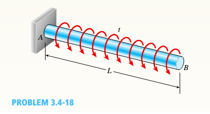
Chapter 3, Problem 3.4.18P
A prismatic bar AB of length L and solid circular cross section (diameter d) is loaded by a distributed torque of constant intensity t per unit distance (sec figure).
- Determine the maximum shear stress tmaxin the bar.
Expert Solution & Answer

Trending nowThis is a popular solution!

Students have asked these similar questions
Only question 2
Only question 1
Only question 3
Chapter 3 Solutions
Bundle: Mechanics Of Materials, Loose-leaf Version, 9th + Mindtap Engineering, 2 Terms (12 Months) Printed Access Card
Ch. 3 - A circular tube is subjected to torque Tat its...Ch. 3 - -2. A plastic bar of diameter d = 56 mm is to be...Ch. 3 - A copper rod of length L = 18.0 in. is to be...Ch. 3 - A circular steel tube of length L = 1.0 m is...Ch. 3 - Solve the preceding problem if the length L = 56...Ch. 3 - A circular aluminum tube subjected to pure torsion...Ch. 3 - A solid steel bar of circular cross section has...Ch. 3 - A solid copper bar of circular cross section has...Ch. 3 - Repeat Problem 3.3-1, but now use a circular tube...Ch. 3 - A copper tube with circular cross section has...
Ch. 3 - A prospector uses a hand-powered winch (see...Ch. 3 - When drilling a hole in a table leg, a furniture...Ch. 3 - While removing a wheel to change a tire, a driver...Ch. 3 - -8 An aluminum bar of solid circular cross section...Ch. 3 - A high-strength steel drill rod used for boring a...Ch. 3 - The steel shaft of a socket wrench has a diameter...Ch. 3 - A circular tube of aluminum is subjected to...Ch. 3 - A propeller shaft for a small yacht is made of a...Ch. 3 - Three identical circular disks A, B, and Care...Ch. 3 - The steel axle of a large winch on an ocean liner...Ch. 3 - A hollow steel shaft used in a construction auger...Ch. 3 - Solve the preceding problem if the shaft has an...Ch. 3 - A vertical pole of solid, circular cross section...Ch. 3 - A vertical pole of solid, circular cross section...Ch. 3 - A solid brass bar of diameter d = 1.25 in. is...Ch. 3 - A hollow aluminum tube used in a roof structure...Ch. 3 - A circular tube of inner radius r1and outer radius...Ch. 3 - .1 A stepped shaft ABC consisting of two solid...Ch. 3 - A circular tube of outer diameter d3= 70 mm and...Ch. 3 - A stepped shaft ABCD consisting of solid circular...Ch. 3 - A solid, circular bar ABC consists of two...Ch. 3 - A hollow tube ABCDE constructed of monel metal is...Ch. 3 - A shaft with a solid, circular cross section...Ch. 3 - Prob. 3.4.7PCh. 3 - Two sections of steel drill pipe, joined by bolted...Ch. 3 - Prob. 3.4.9PCh. 3 - -10. A tapered bar AB with a solid circular cross...Ch. 3 - A tapered bar AB with a solid circular cross...Ch. 3 - The bar shown in the figure is tapered linearly...Ch. 3 - The non prismatic, cantilever circular bar shown...Ch. 3 - A uniformly tapered tube AB with a hollow circular...Ch. 3 - A uniformly tapered aluminum-alloy tube AB with a...Ch. 3 - For the thin nonprismatic steel pipe of constant...Ch. 3 - .17 A mountain-bike rider going uphill applies...Ch. 3 - A prismatic bar AB of length L and solid circular...Ch. 3 - A prismatic bar AB with a solid circular cross...Ch. 3 - A magnesium-alloy wire of diameter d = 4mm and...Ch. 3 - A nonprismatic bar ABC with a solid circular cross...Ch. 3 - -22 Two tubes (AB, BC) of the same material arc...Ch. 3 - A circular copper bar with diameter d = 3 in. is...Ch. 3 - A circular steel tube with an outer diameter of 75...Ch. 3 - A hollow aluminum shaft (see figure) has an...Ch. 3 - A hollow steel bar (G = 80 GPa ) is twisted by...Ch. 3 - A tubular bar with outside diameterd2= 4.0 in, is...Ch. 3 - A solid circular bar of diameter d = 50 mm (see...Ch. 3 - -7 A steel tube (G = 11.5 x 10⁶ psi) has an outer...Ch. 3 - A solid circular bar of steel (G = 78 GPa)...Ch. 3 - The normal strain in the 45n direction on the...Ch. 3 - An aluminum tube has inside diameter dx= 50 mm,...Ch. 3 - -11 A solid steel bar (G = 11.8 X 10⁶ psi ) of...Ch. 3 - A solid aluminum bar (G = 27 GPa ) of diameter d =...Ch. 3 - Two circular aluminum pipes of equal length L = 24...Ch. 3 - A generator shaft in a small hydroelectric plant...Ch. 3 - A motor drives a shaft at 12 Hz and delivers 20 kW...Ch. 3 - A motor driving a solid circular steel shaft with...Ch. 3 - Prob. 3.7.4PCh. 3 - The propeller shaft of a large ship has an outside...Ch. 3 - The drive shaft for a truck (outer diameter 60 mm...Ch. 3 - A hollow circular shaft for use in a pumping...Ch. 3 - A tubular shaft being designed for use on a...Ch. 3 - A propeller shaft of solid circular cross section...Ch. 3 - What is the maximum power that can be delivered by...Ch. 3 - A motor delivers 275 hp at 1000 rpm to the end of...Ch. 3 - Prob. 3.7.12PCh. 3 - A solid circular bar ABCD with fixed supports is...Ch. 3 - A solid circular bar A BCD with fixed supports at...Ch. 3 - A solid circular shaft AB of diameter d is fixed...Ch. 3 - A ho 1 low st e el shaft ACB of outside diameter...Ch. 3 - A stepped shaft ACB having solid circular cross...Ch. 3 - A stepped shaft ACB having solid circular cross...Ch. 3 - A stepped shaft ACE is held against rotation at...Ch. 3 - A solid circulai' aluminum bar AB is fixed at both...Ch. 3 - Two sections of steel drill pipe, joined by bolted...Ch. 3 - A circular bar AB of length L is fixed against...Ch. 3 - A circular bar AB with ends fixed against rotation...Ch. 3 - A solid steel bar of diameter d1= 25.0 mm is...Ch. 3 - A solid steel bar of diameter d1= 1.50 in. is...Ch. 3 - The composite shaft shown in the figure is...Ch. 3 - The composite shaft shown in the figure is...Ch. 3 - A steel shaft (Gs= 80 GPa) of total length L = 3.0...Ch. 3 - A uniformly tapered aluminum-ally tube AB of...Ch. 3 - Two pipes {L, = 2.5 m and L, = 1.5 m) are joined...Ch. 3 - A solid circular bar of steel (G = 1L4 × 106 psi)...Ch. 3 - A solid circular bar of copper (G = 45 GPa) with...Ch. 3 - A stepped shaft of solid circular cross sections...Ch. 3 - A stepped shaft of solid circular cross sections...Ch. 3 - A circular tube AB is fixed at one end and free at...Ch. 3 - A cantilever bar of circular cross section and...Ch. 3 - Obtain a formula for the strain energy U of the...Ch. 3 - A statically indeterminate stepped shaft ACE is...Ch. 3 - Derive a formula for the strain energy U of the...Ch. 3 - A thin-walled hollow tube AB of conical shape has...Ch. 3 - A hollow circular tube A fits over the end of a...Ch. 3 - A heavy flywheel rotating at n revolutions per...Ch. 3 - A hollow circular tube having an inside diameter...Ch. 3 - A solid circular bar having diameter d is to be...Ch. 3 - A thin-walled aluminum tube of rectangular cross...Ch. 3 - A thin-walled steel tube of rectangular cross...Ch. 3 - A square tube section has side dimension of 20 in....Ch. 3 - A thin-walled circular tube and a solid circular...Ch. 3 - A thin-walled steel tube having an elliptical...Ch. 3 - Calculate the shear stress and the angle of twist...Ch. 3 - A torque T is applied to a thin-walled tube having...Ch. 3 - Compare the angle of twist 1 for a thin-walled...Ch. 3 - A tubular aluminum bar (G = 4 × 10⁶ psi) of square...Ch. 3 - A thin tubular shaft with a circular cross section...Ch. 3 - A thin-walled rectangular tube has uniform...Ch. 3 - A long, thin-walled tapered tube AB with a...Ch. 3 - A stepped shaft consisting of solid circular...Ch. 3 - A stepped shaft with diameters D1= 40 mm and D2=...Ch. 3 - A full quarter-circular fillet is used at the...Ch. 3 - The stepped shaft shown in the figure is required...Ch. 3 - A stepped shaft (see figure) has diameter D2= 1.5...
Knowledge Booster


Learn more about
Need a deep-dive on the concept behind this application? Look no further. Learn more about this topic, mechanical-engineering and related others by exploring similar questions and additional content below.Similar questions
- I have Euler parameters that describe the orientation of N relative to Q, e = -0.7071*n3, e4 = 0.7071. I have Euler parameters that describe the orientation of U relative to N, e = -1/sqrt(3)*n1, e4 = sqrt(2/3). After using euler parameter rule of successive rotations, I get euler parameters that describe the orientation of U relative to Q, e = -0.4082*n1 - 0.4082*n2 - 0.5774*n3. I need euler parameters that describe the orientation of U relative to Q in vector basis of q instead of n. How do I get that?arrow_forwardDescribe at least 4 processes in engineering where control charts are (or should be) appliedarrow_forwardDescribe at least two (2) processes where control charts are (or should be) applied.arrow_forward
- Problem 3: A cube-shaped spacecraft is in a circular Earth orbit. Let N (n,) be inertial and the spacecraft is denoted S (ŝ₁). The spacecraft is described such that ¯½º = J ŝ₁ŝ₁ + J ŝ₂§₂ + J §¸Ŝ3 Location of the spacecraft in the orbit is determined by the orbit-fixed unit vectors ê, that are oriented by the angle (Qt), where is a constant angular rate. 52 €3 3> 2t 55 Λ Из At the instant when Qt = 90°, the spacecraft S is oriented relative to the orbit such that 8₁ = 0° Space-three 1-2-3 angles 0₂ = 60° and ES = $₂ rad/s 0₁ = 135° (a) At this instant, determine the direction cosine matrix that describes the orientation of the spacecraft with respect to the inertial frame N.arrow_forwardThis problem illustrates that the factor of safety for a machine element depends on the particular point selected for analysis. Here you are to compute factors of safety, based upon the distortion-energy theory, for stress elements at A and B of the member shown in the figure. This bar is made of AISI 1006 cold-drawn steel and is loaded by the forces F = 1.100 kN, P = 8.00 kN, and T = 50.00 N-m. Given: Sy = 280 MPa. B -100 mm- 15-mm D. a) Determine the value of the axial stress at point B. b) Determine the value of the shear stress at point B. c) Determine the value of the Von Mises stress at point B. P Farrow_forwardA piston-cylinder device initially contains 0.08 m^3 of nitrogen gas at 130 kPa and 170°C. The nitrogen is expanded to a pressure of 80 kPa via isentropic expansion. Determine the final temperature and the boundary work done by the system during this process.arrow_forward
- A Carnot (ideal) heat pump is to be used to heat a house and maintain it at 22°C in winter. On a day when the average outdoor temperature remains at about 0°C, the house is estimated to lose heat at a rate of 65,000 kJ/h. If the heat pump consumes 6 kW of power while operating, determine: (a) how long the heat pump ran on that day (b) the total heating costs, assuming an average price of 11¢/kWh for electricity (c) the heating cost for the same day if an 85% efficient electric furnace is used instead of a heat pump.arrow_forwardFrom the information in the image, I needed to find the orientation of U relative to Q in vector basis q_hat. I transformed the euler angle/axis representation to euler parameters. Then I got its conjugate in order to get the euler parameter in N frame relative to Q. The problem gave the euler angle/axis representation in Q frame relative to N, so I needed to find the conjugate. Then I used the euler parameter rule of successive rotation to find the final euler parameters that describe the orientation of U relative to Q. However that orientation is in n_hat which is the intermediate frame. How do I get the final result in q_hat?arrow_forwardA proposed method of power generation involves collecting and storing solar energy in large artificial lakes a few meters deep, called solar ponds. Solar energy is absorbed by all parts of the pond, and the water temperature rises everywhere. The top part of the pond, however, loses much of the heat it absorbs to the atmosphere, and as a result, the cool surface water serves as insulation for the bottom part of the pond and helps trap the energy there. Usually, salt is planted at the bottom of the pond to prevent the rise of this hot water to the top. A heat engine that uses an organic fluid, such as alcohol, as the working fluid can be operated between the top and the bottom portions of the pond. If the water temperature is 27°C near the surface and 72°C near the bottom of the pond, determine the maximum thermal efficiency that this power plant can have. Treat the cycle as an ideal heat engine. Would a heat engine operating under these temperature conditions (27°C and 72°C) be…arrow_forward
- A standard Carnot heat engine cycle is executed in a closed system between the temperature limits of 320 and 1350 K, with air as the working fluid. The pressures before and after the isothermal compression are 150 and 300 kPa, respectively. Sketch the TS diagram for this cycle. If the net work output per cycle is 0.75 kJ, determine the efficiency of the cycle and the heat transfer to the air (working fluid) per cycle.arrow_forwardPROBLEM 10: A sleeve in the form of a circular tube of length L is Nut placed around a bolt and fitted between washers at each end. The nut is then turned until it is just snug. Use material properties as follows: For the sleeve, as = 21 x 106/°C and Es = 100 GPa Washer Bolt ·L· Sleeve Bolt head For the bolt, αB = 10 × 10-6/°C and EB = 200 GPa. 1. Calculate the temperature rise that is required to produce a compressive stress of 25 MPa in the sleeve.arrow_forwardThis problem illustrates that the factor of safety for a machine element depends on the particular point selected for analysis. Here you are to compute factors of safety, based upon the distortion-energy theory, for stress elements at A and B of the member shown in the figure. This bar is made of AISI 1006 cold-drawn steel and is loaded by the forces F = 1.100 kN, P = 8.00 kN, and T = 50.00 N·m. Given: Sy = 280 MPa. B -100 mm- 15-mm D. a) What is the value of the axial stress at point A? b)What is the value of the shear stress at point A? c)Determine the value of the Von Mises stress at point A. P Farrow_forward
arrow_back_ios
SEE MORE QUESTIONS
arrow_forward_ios
Recommended textbooks for you
 Mechanics of Materials (MindTap Course List)Mechanical EngineeringISBN:9781337093347Author:Barry J. Goodno, James M. GerePublisher:Cengage Learning
Mechanics of Materials (MindTap Course List)
Mechanical Engineering
ISBN:9781337093347
Author:Barry J. Goodno, James M. Gere
Publisher:Cengage Learning
Everything About COMBINED LOADING in 10 Minutes! Mechanics of Materials; Author: Less Boring Lectures;https://www.youtube.com/watch?v=N-PlI900hSg;License: Standard youtube license