
Statics and Mechanics of Materials Plus Mastering Engineering with Pearson eText - Access Card Package (5th Edition)
5th Edition
ISBN: 9780134301006
Author: Russell C. Hibbeler
Publisher: PEARSON
expand_more
expand_more
format_list_bulleted
Videos
Textbook Question
Chapter 2.9, Problem 90P
Determine the magnitude of the projected component of the force acting along line OA.
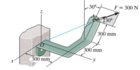
Prob. 2–90
Expert Solution & Answer
Want to see the full answer?
Check out a sample textbook solution
Students have asked these similar questions
only 41
Normal and tangential components-relate to x-y coordinates
A race car enters the circular portion of a track that has a radius of 65 m. When the car enters the curve at point P, it is traveling with a speed of 120 km/h that is increasing at 5 m/s^2 . Three seconds later, determine the x and y components of velocity and acceleration of the car. I need help with finding the y component of the total acceleration. I had put -32 but its incorrect. but i keep getting figures around that number
The bracket BCD is hinged at C and attached to a control cable at B. Let F₁ = 275 N and F2 = 275 N.
F1
B
a=0.18 m
C
A
0.4 m
-0.4 m-
0.24 m
Determine the reaction at C.
The reaction at C
N Z
F2
D
Chapter 2 Solutions
Statics and Mechanics of Materials Plus Mastering Engineering with Pearson eText - Access Card Package (5th Edition)
Ch. 2.3 - In each case, construct the parallelogram law to...Ch. 2.3 - In each case, show how to resolve the force F into...Ch. 2.3 - Determine the magnitude of the resultant force...Ch. 2.3 - Determine the magnitude of the resultant force....Ch. 2.3 - Determine the magnitude of the resultant force and...Ch. 2.3 - Resolve the 30-lb force into components along the...Ch. 2.3 - Resolve the force into components acting along...Ch. 2.3 - Prob. 6FPCh. 2.3 - If = 60 and F = 450 N, determine the magnitude of...Ch. 2.3 - If the magnitude of the resultant force is to be...
Ch. 2.3 - Determine the magnitude of the resultant force FR...Ch. 2.3 - Determine the magnitudes of the two components of...Ch. 2.3 - Solve Prob. 24 with F = 350 lb. 24. Determine the...Ch. 2.3 - Determine the magnitude of the resultant force FR...Ch. 2.3 - Resolve the force F1 into components acting along...Ch. 2.3 - Resolve the force F2 into components acting along...Ch. 2.3 - If the resultant force acting on the support is to...Ch. 2.3 - Determine the magnitude of the resultant force and...Ch. 2.3 - If = 60, determine the magnitude of the resultant...Ch. 2.3 - Determine the angle for connecting member A to...Ch. 2.3 - The force acting on the gear tooth is F = 20 lb....Ch. 2.3 - The component of force F acting along line aa is...Ch. 2.3 - Force F acts on the frame such that its component...Ch. 2.3 - Force F acts on the frame such that its component...Ch. 2.3 - If F1 = 30 lb and F2 = 40 lb, determine the angles...Ch. 2.3 - Determine the magnitude and direction of FA so...Ch. 2.3 - Determine the magnitude of the resultant force...Ch. 2.3 - Prob. 20PCh. 2.3 - If the resultant force of the two tugboats is 3...Ch. 2.3 - If FB = 3 kN and = 45, determine the magnitude of...Ch. 2.3 - If the resultant force of the two tugboats is...Ch. 2.4 - Resolve each force into its x and y components....Ch. 2.4 - F28. Determine the magnitude and direction of the...Ch. 2.4 - Prob. 9FPCh. 2.4 - Prob. 10FPCh. 2.4 - Prob. 11FPCh. 2.4 - Determine the magnitude of the resultant force and...Ch. 2.4 - Determine the magnitude of the resultant force and...Ch. 2.4 - Prob. 25PCh. 2.4 - Prob. 26PCh. 2.4 - Determine the magnitude of the resultant force and...Ch. 2.4 - Prob. 28PCh. 2.4 - Determine the magnitude of the resultant force...Ch. 2.4 - Prob. 30PCh. 2.4 - Prob. 31PCh. 2.4 - Prob. 32PCh. 2.4 - Determine the magnitude of the resultant force and...Ch. 2.4 - Prob. 34PCh. 2.4 - Prob. 35PCh. 2.4 - Determine the magnitude of the resultant force and...Ch. 2.4 - Determine the magnitude and direction of the...Ch. 2.6 - Sketch the following forces on the x, y, z...Ch. 2.6 - In each case, establish F as a Cartesian vector,...Ch. 2.6 - Show how to resolve each force into its x, y, z...Ch. 2.6 - Determine the coordinate direction angles of the...Ch. 2.6 - Prob. 14FPCh. 2.6 - Prob. 15FPCh. 2.6 - Prob. 16FPCh. 2.6 - Prob. 17FPCh. 2.6 - Determine the resultant force acting on the hook....Ch. 2.6 - The force F has a magnitude of 80 lb. Determine...Ch. 2.6 - The bolt is subjected to the force F, which has...Ch. 2.6 - Determine the magnitude and coordinate direction...Ch. 2.6 - Prob. 41PCh. 2.6 - Prob. 42PCh. 2.6 - Express each force in Cartesian vector form and...Ch. 2.6 - Prob. 44PCh. 2.6 - Determine the magnitude and coordinate direction...Ch. 2.6 - Determine the magnitude and coordinate direction...Ch. 2.6 - Prob. 47PCh. 2.6 - Determine the magnitude and coordinate direction...Ch. 2.6 - Prob. 49PCh. 2.6 - Prob. 50PCh. 2.6 - Prob. 51PCh. 2.6 - Determine the magnitude and coordinate direction...Ch. 2.6 - Prob. 53PCh. 2.6 - Prob. 54PCh. 2.6 - Determine the magnitude and coordinate direction...Ch. 2.8 - In each case, establish a position vector from...Ch. 2.8 - In each case, express F as a Cartesian vector. (a)...Ch. 2.8 - Prob. 19FPCh. 2.8 - Determine the length of the rod and the position...Ch. 2.8 - Prob. 21FPCh. 2.8 - Express the force as a Cartesian vector. Prob....Ch. 2.8 - Prob. 23FPCh. 2.8 - Prob. 24FPCh. 2.8 - Determine the length of the connecting rod AB by...Ch. 2.8 - Express force F as a Cartesian vector; then...Ch. 2.8 - Express each force as a Cartesian vector, and then...Ch. 2.8 - If F = {350i 250j 450k} N and cable AB is 9 m...Ch. 2.8 - The 8-m-long cable is anchored to the ground at A....Ch. 2.8 - The 8-m-long cable is anchored to the ground at A....Ch. 2.8 - Express each of the forces in Cartesian vector...Ch. 2.8 - If FB = 560 N and FC = 700 N, determine the...Ch. 2.8 - If FB = 700 N, and FC = 560 N, determine the...Ch. 2.8 - The plate is suspended using the three cables...Ch. 2.8 - Prob. 66PCh. 2.8 - Determine the magnitude and coordinate direction...Ch. 2.8 - Prob. 68PCh. 2.8 - The load at A creates a force of 60 lb in wire AB....Ch. 2.8 - Determine the magnitude and coordinate direction...Ch. 2.9 - In each case, set up the dot product to find the...Ch. 2.9 - In each case, set up the dot product to find the...Ch. 2.9 - Determine the angle between the force and the...Ch. 2.9 - Determine the angle between the force and the...Ch. 2.9 - Determine the angle between the force and the...Ch. 2.9 - Determine the projected component of the force...Ch. 2.9 - Find the magnitude of the projected component of...Ch. 2.9 - Determine the components of the force acting...Ch. 2.9 - Prob. 31FPCh. 2.9 - Prob. 71PCh. 2.9 - Determine the magnitudes of the components of F =...Ch. 2.9 - Determine the angle between BA and BC. Probs. 273Ch. 2.9 - Determine the magnitude of the projected component...Ch. 2.9 - Prob. 75PCh. 2.9 - Determine the magnitude of the projection of the...Ch. 2.9 - Determine the angle between the pole and the wire...Ch. 2.9 - Determine the magnitude of the projection of the...Ch. 2.9 - Determine the magnitude of the projected component...Ch. 2.9 - Prob. 80PCh. 2.9 - Determine the angle between the two cables. Prob....Ch. 2.9 - Determine the projected component of the force...Ch. 2.9 - Determine the angles and between the flag pole...Ch. 2.9 - Determine the magnitudes of the components of F...Ch. 2.9 - Prob. 85PCh. 2.9 - Determine the angle between the pipe segments BA...Ch. 2.9 - If the force F = 100 N lies in the plane DBEC,...Ch. 2.9 - Determine the magnitudes of the components of the...Ch. 2.9 - Determine the magnitudes of the projected...Ch. 2.9 - Determine the magnitude of the projected component...Ch. 2.9 - Two cables exert forces on the pipe. Determine the...Ch. 2.9 - Determine the angle between the two forces. Prob....Ch. 2 - Determine the magnitude of the resultant force FR...Ch. 2 - Resolve the force into components along the u and...Ch. 2 - Determine the magnitude of the resultant force...Ch. 2 - The cable exerts a force of 250 lb on the crane...Ch. 2 - The cable attached to the tractor at B exerts a...Ch. 2 - Express F1 and F2 as Cartesian vectors. Prob. R26Ch. 2 - Determine the angle between the edges of the...Ch. 2 - Determine the projection of the force F along the...
Knowledge Booster


Learn more about
Need a deep-dive on the concept behind this application? Look no further. Learn more about this topic, mechanical-engineering and related others by exploring similar questions and additional content below.Similar questions
- Consider the angle bar shown in the given figure A W 240 mm B 80 mm Draw the free-body diagram needed to determine the reactions at A and B when a = 150 mm. This problem could also be approached as a 3-force body using method of Section 4.2B.arrow_forwardA telemetry system is used to quantify kinematic values of a ski jumper immediately before the jumper leaves the ramp. According to the system r=560 ft , r˙=−105 ft/s , r¨=−10 ft/s2 , θ=25° , θ˙=0.07 rad/s , θ¨=0.06 rad/s2 Determine the velocity of the skier immediately before leaving the jump. The velocity of the skier immediately before leaving the jump along with its direction is ? I have 112.08 ft/s but can't seem to get the direction correct. Determine the acceleration of the skier at this instant. At this instant, the acceleration of the skier along with its direction is ? acceleration is 22.8 ft/s^2 but need help with direction. Need help with velocity direction and acceleration direction please.arrow_forwardFor the stop bracket shown, locate the x coordinate of the center of gravity. Consider a = = 16.50 mm. 34 mm 62 mm 51 mm 10 mm 100 mm 88 mm 55 mm 45 mm The x coordinate of the center of gravity is mm.arrow_forward
- In the given figure, the bent rod ABEF is supported by bearings at C and D and by wire AH. The portion AB of the rod is 250 mm long, and the load W is 580 N. Assume that the bearing at D does not exert any axial thrust. H B A с 30° 250 mm D Z 50 mm 300 mm F 250 mm 50 mm W Draw the free-body diagram needed to determine the tension in wire AH and the reactions at C and D.arrow_forwardA 10-ft boom is acted upon by the 810-lb force as shown in the figure. D 6 ft 6 ft E B 7 ft C 6 ft x 4 ft W Draw the free-body diagram needed to determine the tension in each cable and the reaction at the ball-and-socket joint at A.arrow_forwardLocate the center of gravity of the sheet-metal form shown. Given: r = 26.40 mm . 50 mm 40 mm X 150 mm The center of gravity (✗) of the sheet-metal form is The center of gravity (Y) of the sheet-metal form is The center of gravity ( Z ) of the sheet-metal form is mm. mm. (Round the final answer to three decimal places.) mm.arrow_forward
- Determine the reactions at the beam supports for the given loading if W = 300 lb/ft . W 6 ft A 9 ft. 6 ft- The reaction at Bis lb. The reaction at A is lb. Barrow_forwardIn the given figure, the bent rod ABEF is supported by bearings at C and D and by wire AH. The portion AB of the rod is 250 mm long, and the load W is 580 N. Assume that the bearing at D does not exert any axial thrust. 30° 250 mm 300 mm 50 mm H B C D 50 mm W 250 mm Determine the reactions at C and D. (Include a minus sign if necessary.) The reaction at Cis N) j + N)k The reaction at Dis N) j + ( N)karrow_forwardConsider the angle bar shown in the given figure A B W 240 mm- 80 mm Determine the reactions at A and B when a = 150 mm and W = 320 N. The reaction at A is N ZI The reaction at Bis N.arrow_forward
- In the given figure, the bent rod ABEF is supported by bearings at C and D and by wire AH. The portion AB of the rod is 250 mm long, and the load W is 580 N. Assume that the bearing at D does not exert any axial thrust. H B A 30° 250 mm D 300 mm 50 mm 50 mm W Determine the tension in wire AH. The tension in wire AH is N. 250 mm xarrow_forwardExposure to high concentrations of gaseous ammonia can cause lung damage. The acceptable short term ammonia exposure level set by the occupational safety and health administration is 35 ppm for 15 min. consider a vessel filled with gaseous ammonia at 30 mol/L and 10 cm diameter circular plastic plug with thickeness of 2 mm is used to contain the ammonia inside the vessel. the ventilation system is capable of keeping the room safe with fresh air, provded that the rate of ammonia being release is below .2 mg/s. if the diffusion coefficient of ammonia through the plug is 1.3*10^-10 m^2/s, determine whether or not the plug can safelt contain the ammonia inside the vessel.arrow_forwardThe state of stress at a point is σ = -8.00 kpsi, σy = 12.00 kpsi, σ% = -18.00 kpsi, Try = 7.00 kpsi, Tyz = 4.000 kpsi, and Tzx = -18.00 kpsi. Determine the principal stresses. The principal normal stress σ1 is determined to be kpsi. The principal normal stress σ2 is determined to be The principal normal stress σ3 is determined to be kpsi. kpsi. The principal shear stress T₁ T1/2 is determined to be kpsi. The principal shear stress 72/ is determined to be [ kpsi. The principal shear stress T1/3 is determined to be kpsi.arrow_forward
arrow_back_ios
SEE MORE QUESTIONS
arrow_forward_ios
Recommended textbooks for you
 Elements Of ElectromagneticsMechanical EngineeringISBN:9780190698614Author:Sadiku, Matthew N. O.Publisher:Oxford University Press
 Mechanics of Materials (10th Edition)Mechanical EngineeringISBN:9780134319650Author:Russell C. HibbelerPublisher:PEARSON
 Thermodynamics: An Engineering ApproachMechanical EngineeringISBN:9781259822674Author:Yunus A. Cengel Dr., Michael A. BolesPublisher:McGraw-Hill Education
 Control Systems EngineeringMechanical EngineeringISBN:9781118170519Author:Norman S. NisePublisher:WILEY
 Mechanics of Materials (MindTap Course List)Mechanical EngineeringISBN:9781337093347Author:Barry J. Goodno, James M. GerePublisher:Cengage Learning
 Engineering Mechanics: StaticsMechanical EngineeringISBN:9781118807330Author:James L. Meriam, L. G. Kraige, J. N. BoltonPublisher:WILEY
Elements Of Electromagnetics
Mechanical Engineering
ISBN:9780190698614
Author:Sadiku, Matthew N. O.
Publisher:Oxford University Press
Mechanics of Materials (10th Edition)
Mechanical Engineering
ISBN:9780134319650
Author:Russell C. Hibbeler
Publisher:PEARSON
Thermodynamics: An Engineering Approach
Mechanical Engineering
ISBN:9781259822674
Author:Yunus A. Cengel Dr., Michael A. Boles
Publisher:McGraw-Hill Education
Control Systems Engineering
Mechanical Engineering
ISBN:9781118170519
Author:Norman S. Nise
Publisher:WILEY
Mechanics of Materials (MindTap Course List)
Mechanical Engineering
ISBN:9781337093347
Author:Barry J. Goodno, James M. Gere
Publisher:Cengage Learning
Engineering Mechanics: Statics
Mechanical Engineering
ISBN:9781118807330
Author:James L. Meriam, L. G. Kraige, J. N. Bolton
Publisher:WILEY
How to balance a see saw using moments example problem; Author: Engineer4Free;https://www.youtube.com/watch?v=d7tX37j-iHU;License: Standard Youtube License