
Statics and Mechanics of Materials Plus Mastering Engineering with Pearson eText - Access Card Package (5th Edition)
5th Edition
ISBN: 9780134301006
Author: Russell C. Hibbeler
Publisher: PEARSON
expand_more
expand_more
format_list_bulleted
Videos
Textbook Question
Chapter 2.6, Problem 13FP
Determine the coordinate direction angles of the force.
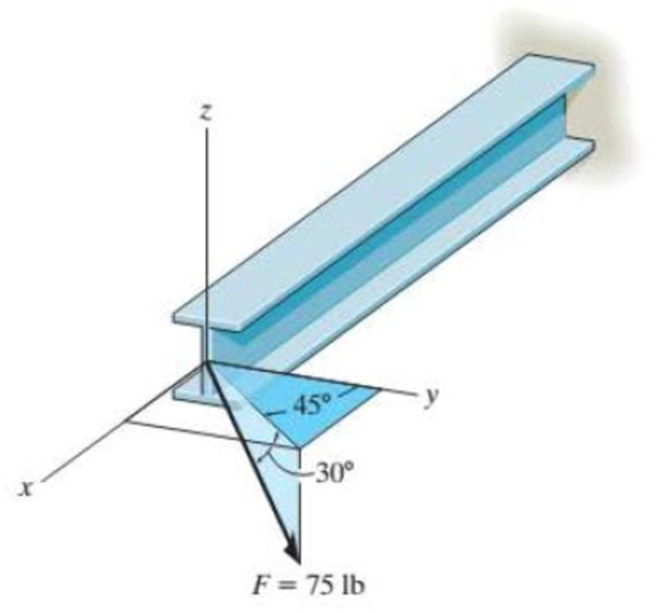
Prob. F2–13
Expert Solution & Answer
Want to see the full answer?
Check out a sample textbook solution
Students have asked these similar questions
For the first part: d = 4 cm, and Q = 15 Liters/s. For the second part Q = 6 Liters/s, and D = 80 cm
Q.2: (15 Marks)
=
1400
For the following system, determine the first natural frequency using Dunkerley's equation,
Given that the disk has moment of inertia J = 2 kg.m², the shaft has G = 20 GPa, p
kg/m³, polar moment of cross-sectional area of the shaft Ip = 8×10⁸ m².
500 mm
220 mm
k=200 N/m
FOF
m=1 kg
14.14
56.56. W
сл
1 Revolute four-bar mechanism, AB=60mm, BC=130mm, CD=140mm, AD=200mm,
Chapter 2 Solutions
Statics and Mechanics of Materials Plus Mastering Engineering with Pearson eText - Access Card Package (5th Edition)
Ch. 2.3 - In each case, construct the parallelogram law to...Ch. 2.3 - In each case, show how to resolve the force F into...Ch. 2.3 - Determine the magnitude of the resultant force...Ch. 2.3 - Determine the magnitude of the resultant force....Ch. 2.3 - Determine the magnitude of the resultant force and...Ch. 2.3 - Resolve the 30-lb force into components along the...Ch. 2.3 - Resolve the force into components acting along...Ch. 2.3 - Prob. 6FPCh. 2.3 - If = 60 and F = 450 N, determine the magnitude of...Ch. 2.3 - If the magnitude of the resultant force is to be...
Ch. 2.3 - Determine the magnitude of the resultant force FR...Ch. 2.3 - Determine the magnitudes of the two components of...Ch. 2.3 - Solve Prob. 24 with F = 350 lb. 24. Determine the...Ch. 2.3 - Determine the magnitude of the resultant force FR...Ch. 2.3 - Resolve the force F1 into components acting along...Ch. 2.3 - Resolve the force F2 into components acting along...Ch. 2.3 - If the resultant force acting on the support is to...Ch. 2.3 - Determine the magnitude of the resultant force and...Ch. 2.3 - If = 60, determine the magnitude of the resultant...Ch. 2.3 - Determine the angle for connecting member A to...Ch. 2.3 - The force acting on the gear tooth is F = 20 lb....Ch. 2.3 - The component of force F acting along line aa is...Ch. 2.3 - Force F acts on the frame such that its component...Ch. 2.3 - Force F acts on the frame such that its component...Ch. 2.3 - If F1 = 30 lb and F2 = 40 lb, determine the angles...Ch. 2.3 - Determine the magnitude and direction of FA so...Ch. 2.3 - Determine the magnitude of the resultant force...Ch. 2.3 - Prob. 20PCh. 2.3 - If the resultant force of the two tugboats is 3...Ch. 2.3 - If FB = 3 kN and = 45, determine the magnitude of...Ch. 2.3 - If the resultant force of the two tugboats is...Ch. 2.4 - Resolve each force into its x and y components....Ch. 2.4 - F28. Determine the magnitude and direction of the...Ch. 2.4 - Prob. 9FPCh. 2.4 - Prob. 10FPCh. 2.4 - Prob. 11FPCh. 2.4 - Determine the magnitude of the resultant force and...Ch. 2.4 - Determine the magnitude of the resultant force and...Ch. 2.4 - Prob. 25PCh. 2.4 - Prob. 26PCh. 2.4 - Determine the magnitude of the resultant force and...Ch. 2.4 - Prob. 28PCh. 2.4 - Determine the magnitude of the resultant force...Ch. 2.4 - Prob. 30PCh. 2.4 - Prob. 31PCh. 2.4 - Prob. 32PCh. 2.4 - Determine the magnitude of the resultant force and...Ch. 2.4 - Prob. 34PCh. 2.4 - Prob. 35PCh. 2.4 - Determine the magnitude of the resultant force and...Ch. 2.4 - Determine the magnitude and direction of the...Ch. 2.6 - Sketch the following forces on the x, y, z...Ch. 2.6 - In each case, establish F as a Cartesian vector,...Ch. 2.6 - Show how to resolve each force into its x, y, z...Ch. 2.6 - Determine the coordinate direction angles of the...Ch. 2.6 - Prob. 14FPCh. 2.6 - Prob. 15FPCh. 2.6 - Prob. 16FPCh. 2.6 - Prob. 17FPCh. 2.6 - Determine the resultant force acting on the hook....Ch. 2.6 - The force F has a magnitude of 80 lb. Determine...Ch. 2.6 - The bolt is subjected to the force F, which has...Ch. 2.6 - Determine the magnitude and coordinate direction...Ch. 2.6 - Prob. 41PCh. 2.6 - Prob. 42PCh. 2.6 - Express each force in Cartesian vector form and...Ch. 2.6 - Prob. 44PCh. 2.6 - Determine the magnitude and coordinate direction...Ch. 2.6 - Determine the magnitude and coordinate direction...Ch. 2.6 - Prob. 47PCh. 2.6 - Determine the magnitude and coordinate direction...Ch. 2.6 - Prob. 49PCh. 2.6 - Prob. 50PCh. 2.6 - Prob. 51PCh. 2.6 - Determine the magnitude and coordinate direction...Ch. 2.6 - Prob. 53PCh. 2.6 - Prob. 54PCh. 2.6 - Determine the magnitude and coordinate direction...Ch. 2.8 - In each case, establish a position vector from...Ch. 2.8 - In each case, express F as a Cartesian vector. (a)...Ch. 2.8 - Prob. 19FPCh. 2.8 - Determine the length of the rod and the position...Ch. 2.8 - Prob. 21FPCh. 2.8 - Express the force as a Cartesian vector. Prob....Ch. 2.8 - Prob. 23FPCh. 2.8 - Prob. 24FPCh. 2.8 - Determine the length of the connecting rod AB by...Ch. 2.8 - Express force F as a Cartesian vector; then...Ch. 2.8 - Express each force as a Cartesian vector, and then...Ch. 2.8 - If F = {350i 250j 450k} N and cable AB is 9 m...Ch. 2.8 - The 8-m-long cable is anchored to the ground at A....Ch. 2.8 - The 8-m-long cable is anchored to the ground at A....Ch. 2.8 - Express each of the forces in Cartesian vector...Ch. 2.8 - If FB = 560 N and FC = 700 N, determine the...Ch. 2.8 - If FB = 700 N, and FC = 560 N, determine the...Ch. 2.8 - The plate is suspended using the three cables...Ch. 2.8 - Prob. 66PCh. 2.8 - Determine the magnitude and coordinate direction...Ch. 2.8 - Prob. 68PCh. 2.8 - The load at A creates a force of 60 lb in wire AB....Ch. 2.8 - Determine the magnitude and coordinate direction...Ch. 2.9 - In each case, set up the dot product to find the...Ch. 2.9 - In each case, set up the dot product to find the...Ch. 2.9 - Determine the angle between the force and the...Ch. 2.9 - Determine the angle between the force and the...Ch. 2.9 - Determine the angle between the force and the...Ch. 2.9 - Determine the projected component of the force...Ch. 2.9 - Find the magnitude of the projected component of...Ch. 2.9 - Determine the components of the force acting...Ch. 2.9 - Prob. 31FPCh. 2.9 - Prob. 71PCh. 2.9 - Determine the magnitudes of the components of F =...Ch. 2.9 - Determine the angle between BA and BC. Probs. 273Ch. 2.9 - Determine the magnitude of the projected component...Ch. 2.9 - Prob. 75PCh. 2.9 - Determine the magnitude of the projection of the...Ch. 2.9 - Determine the angle between the pole and the wire...Ch. 2.9 - Determine the magnitude of the projection of the...Ch. 2.9 - Determine the magnitude of the projected component...Ch. 2.9 - Prob. 80PCh. 2.9 - Determine the angle between the two cables. Prob....Ch. 2.9 - Determine the projected component of the force...Ch. 2.9 - Determine the angles and between the flag pole...Ch. 2.9 - Determine the magnitudes of the components of F...Ch. 2.9 - Prob. 85PCh. 2.9 - Determine the angle between the pipe segments BA...Ch. 2.9 - If the force F = 100 N lies in the plane DBEC,...Ch. 2.9 - Determine the magnitudes of the components of the...Ch. 2.9 - Determine the magnitudes of the projected...Ch. 2.9 - Determine the magnitude of the projected component...Ch. 2.9 - Two cables exert forces on the pipe. Determine the...Ch. 2.9 - Determine the angle between the two forces. Prob....Ch. 2 - Determine the magnitude of the resultant force FR...Ch. 2 - Resolve the force into components along the u and...Ch. 2 - Determine the magnitude of the resultant force...Ch. 2 - The cable exerts a force of 250 lb on the crane...Ch. 2 - The cable attached to the tractor at B exerts a...Ch. 2 - Express F1 and F2 as Cartesian vectors. Prob. R26Ch. 2 - Determine the angle between the edges of the...Ch. 2 - Determine the projection of the force F along the...
Knowledge Booster


Learn more about
Need a deep-dive on the concept behind this application? Look no further. Learn more about this topic, mechanical-engineering and related others by exploring similar questions and additional content below.Similar questions
- CORRECT AND DETAILED HANDWRITTEN SOLUTION WITH FBD ONLY. I WILL UPVOTE THANK YOU. CORRECT ANSWER IS ALREADY PROVIDED. The roof truss shown carries roof loads, where P = 10 kN. The truss is consisting of circular arcs top andbottom chords with radii R + h and R, respectively.Given: h = 1.2 m, R = 10 m, s = 2 m.Allowable member stresses:Tension = 250 MPaCompression = 180 MPa1. If member KL has square section, determine the minimum dimension (mm).2. If member KL has circular section, determine the minimum diameter (mm).3. If member GH has circular section, determine the minimum diameter (mm).ANSWERS: (1) 31.73 mm; (2) 35.81 mm; (3) 18.49 mmarrow_forwardCORRECT AND DETAILED HANDWRITTEN SOLUTION WITH FBD ONLY. I WILL UPVOTE THANK YOU. CORRECT ANSWER IS ALREADY PROVIDED. The cantilevered spandrel beam shown whose depth tapers from d1 to d2, has a constant width of 120mm. It carries a triangularly distributed end reaction.Given: d1 = 600 mm, d2 = 120 mm, L = 1 m, w = 100 kN/m1. Calculate the maximum flexural stress at the support, in kN-m.2. Determine the distance (m), from the free end, of the section with maximum flexural stress.3. Determine the maximum flexural stress in the beam, in MPa.ANSWERS: (1) 4.630 MPa; (2) 905.8688 m; (3) 4.65 MPaarrow_forwardCORRECT AND DETAILED HANDWRITTEN SOLUTION WITH FBD ONLY. I WILL UPVOTE THANK YOU. CORRECT ANSWER IS ALREADY PROVIDED. A concrete wall retains water as shown. Assume that the wall is fixed at the base. Given: H = 3 m, t = 0.5m, Concrete unit weight = 23 kN/m3Unit weight of water = 9.81 kN/m3(Hint: The pressure of water is linearly increasing from the surface to the bottom with intensity 9.81d.)1. Find the maximum compressive stress (MPa) at the base of the wall if the water reaches the top.2. If the maximum compressive stress at the base of the wall is not to exceed 0.40 MPa, what is the maximum allowable depth(m) of the water?3. If the tensile stress at the base is zero, what is the maximum allowable depth (m) of the water?ANSWERS: (1) 1.13 MPa, (2) 2.0 m, (3) 1.20 marrow_forward
- CORRECT AND DETAILED HANDWRITTEN SOLUTION WITH FBD ONLY. I WILL UPVOTE THANK YOU. CORRECT ANSWER IS ALREADY PROVIDED. A short plate is attached to the center of the shaft as shown. The bottom of the shaft is fixed to the ground.Given: a = 75 mm, h = 125 mm, D = 38 mmP1 = 24 kN, P2 = 28 kN1. Calculate the maximum torsional stress in the shaft, in MPa.2. Calculate the maximum flexural stress in the shaft, in MPa.3. Calculate the maximum horizontal shear stress in the shaft, in MPa.ANSWERS: (1) 167.07 MPa; (2) 679.77 MPa; (3) 28.22 MPaarrow_forwardA counter flow double pipe heat exchanger is being used to cool hot oil from 320°F to 285°F using cold water. The water, which flows through the inner tube, enters the heat exchanger at 70°F and leaves at 175°F. The inner tube is ¾-std type L copper. The overall heat transfer coefficient based on the outside diameter of the inner tube is 140 Btu/hr-ft2-°F. Design conditions call for a total heat transfer duty (heat transfer rate between the two fluids) of 20,000 Btu/hr. Determine the required length of this heat exchanger (ft).arrow_forward! Required information A one-shell-pass and eight-tube-passes heat exchanger is used to heat glycerin (cp=0.60 Btu/lbm.°F) from 80°F to 140°F by hot water (Cp = 1.0 Btu/lbm-°F) that enters the thin-walled 0.5-in-diameter tubes at 175°F and leaves at 120°F. The total length of the tubes in the heat exchanger is 400 ft. The convection heat transfer coefficient is 4 Btu/h-ft²°F on the glycerin (shell) side and 70 Btu/h-ft²°F on the water (tube) side. NOTE: This is a multi-part question. Once an answer is submitted, you will be unable to return to this part. Determine the rate of heat transfer in the heat exchanger before any fouling occurs. Correction factor F 1.0 10 0.9 0.8 R=4.0 3.0 2.0.15 1.0 0.8.0.6 0.4 0.2 0.7 0.6 R= T1-T2 12-11 0.5 12-11 0 0.1 0.2 0.3 0.4 0.5 0.6 0.7 0.8 0.9 1.0 (a) One-shell pass and 2, 4, 6, etc. (any multiple of 2), tube passes P= T₁-11 The rate of heat transfer in the heat exchanger is Btu/h.arrow_forward
- ! Required information Air at 25°C (cp=1006 J/kg.K) is to be heated to 58°C by hot oil at 80°C (cp = 2150 J/kg.K) in a cross-flow heat exchanger with air mixed and oil unmixed. The product of heat transfer surface area and the overall heat transfer coefficient is 750 W/K and the mass flow rate of air is twice that of oil. NOTE: This is a multi-part question. Once an answer is submitted, you will be unable to return to this part. Air Oil 80°C Determine the effectiveness of the heat exchanger.arrow_forwardIn an industrial facility, a counter-flow double-pipe heat exchanger uses superheated steam at a temperature of 155°C to heat feed water at 30°C. The superheated steam experiences a temperature drop of 70°C as it exits the heat exchanger. The water to be heated flows through the heat exchanger tube of negligible thickness at a constant rate of 3.47 kg/s. The convective heat transfer coefficient on the superheated steam and water side is 850 W/m²K and 1250 W/m²K, respectively. To account for the fouling due to chemical impurities that might be present in the feed water, assume a fouling factor of 0.00015 m²-K/W for the water side. The specific heat of water is determined at an average temperature of (30 +70)°C/2 = 50°C and is taken to be J/kg.K. Cp= 4181 Water Steam What would be the required heat exchanger area in case of parallel-flow arrangement? The required heat exchanger area in case of parallel-flow arrangement is 1m².arrow_forwardA single-pass crossflow heat exchanger is used to cool jacket water (cp = 1.0 Btu/lbm.°F) of a diesel engine from 190°F to 140°F, using air (Cp = 0.245 Btu/lbm.°F) at inlet temperature of 90°F. Both air flow and water flow are unmixed. If the water and air mass flow rates are 85500 lbm/h and 400,000 lbm/h, respectively, determine the log mean temperature difference for this heat exchanger. Assume the correction factor F to be 0.92. Air flow (unmixed) Water flow (unmixed) The log mean temperature difference of the heat exchanger is °F.arrow_forward
- using the theorem of three moments, find all the reactions and supports, I need concise calculations only. the answers are at the bottom, I need concise steps and minimal explanationsarrow_forwardIn an industrial facility, a counter-flow double-pipe heat exchanger uses superheated steam at a temperature of 155°C to heat feed water at 30°C. The superheated steam experiences a temperature drop of 70°C as it exits the heat exchanger. The water to be heated flows through the heat exchanger tube of negligible thickness at a constant rate of 3.47 kg/s. The convective heat transfer coefficient on the superheated steam and water side is 850 W/m²K and 1250 W/m²K, respectively. To account for the fouling due to chemical impurities that might be present in the feed water, assume a fouling factor of 0.00015 m² K/W for the water side. The specific heat of water is determined at an average temperature of (30+70)°C/2 = 50°C and is taken to be Cp J/kg-K. Water Steam Determine the heat exchanger area required to maintain the exit temperature of the water to a minimum of 70°C. The heat exchanger area required isarrow_forwardStress, ksi 160 72 150- 140 80 70 ༄ ྃ ༈ ཎྜ རྦ ༅ ཎྜ ྣཧྨ ➢ 130 120 110 100 90 2.0 2.8 3.6 4.4 5 Wire diameter, mm 6.0 6.8 2 7.6 8.4 Compression and extension springs. ASTM A227 Class II Light service Average service 0.020 0.060 0.100 0.140 0.180 0.220 0.260 0.300 0.340 0.380 0.420 0.460 0.500 Wire diameter, in Torsional stress due to initial tension, ksi 10 ४ 20 Preferred range 100 Stress, MPa 9.2 10.0 10.8 11.6 12.4 1100 1035 965 895 825 760 Severe service 690 620 550 50 150 3456789 10 11 12 13 14 15 16 Spring index, C = DJD FIGURE 18-21 Recommended torsional shear stress in an extension spring due to initial tension (Data from Associated Spring, Barnes Group, Inc.) 50 200 485 Stress, MPaarrow_forward
arrow_back_ios
SEE MORE QUESTIONS
arrow_forward_ios
Recommended textbooks for you
 Elements Of ElectromagneticsMechanical EngineeringISBN:9780190698614Author:Sadiku, Matthew N. O.Publisher:Oxford University Press
 Mechanics of Materials (10th Edition)Mechanical EngineeringISBN:9780134319650Author:Russell C. HibbelerPublisher:PEARSON
 Thermodynamics: An Engineering ApproachMechanical EngineeringISBN:9781259822674Author:Yunus A. Cengel Dr., Michael A. BolesPublisher:McGraw-Hill Education
 Control Systems EngineeringMechanical EngineeringISBN:9781118170519Author:Norman S. NisePublisher:WILEY
 Mechanics of Materials (MindTap Course List)Mechanical EngineeringISBN:9781337093347Author:Barry J. Goodno, James M. GerePublisher:Cengage Learning
 Engineering Mechanics: StaticsMechanical EngineeringISBN:9781118807330Author:James L. Meriam, L. G. Kraige, J. N. BoltonPublisher:WILEY
Elements Of Electromagnetics
Mechanical Engineering
ISBN:9780190698614
Author:Sadiku, Matthew N. O.
Publisher:Oxford University Press
Mechanics of Materials (10th Edition)
Mechanical Engineering
ISBN:9780134319650
Author:Russell C. Hibbeler
Publisher:PEARSON
Thermodynamics: An Engineering Approach
Mechanical Engineering
ISBN:9781259822674
Author:Yunus A. Cengel Dr., Michael A. Boles
Publisher:McGraw-Hill Education
Control Systems Engineering
Mechanical Engineering
ISBN:9781118170519
Author:Norman S. Nise
Publisher:WILEY
Mechanics of Materials (MindTap Course List)
Mechanical Engineering
ISBN:9781337093347
Author:Barry J. Goodno, James M. Gere
Publisher:Cengage Learning
Engineering Mechanics: Statics
Mechanical Engineering
ISBN:9781118807330
Author:James L. Meriam, L. G. Kraige, J. N. Bolton
Publisher:WILEY
How to balance a see saw using moments example problem; Author: Engineer4Free;https://www.youtube.com/watch?v=d7tX37j-iHU;License: Standard Youtube License