EBK PHYSICS FOR SCIENTISTS AND ENGINEER
1st Edition
ISBN: 9780100546714
Author: Katz
Publisher: YUZU
bartleby

Videos

Textbook Question
Book Icon
Chapter 29, Problem 49PQ

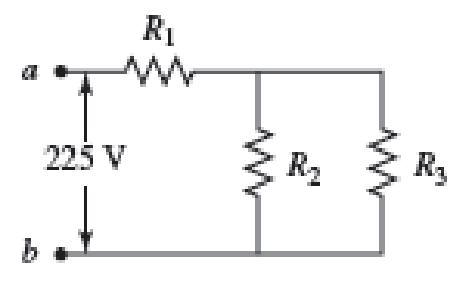
Three resistors with resistances R1 = R/2 and R2 = R3 = R are connected as shown, and a potential difference of 225 V is applied across terminals a and b (Fig. P29.49).

a. If the resistor R1 dissipates 75.0 W of power, what is the value of R?

b. What is the total power supplied to the circuit by the emf?

c. What is the potential difference across each of the three resistors?

Chapter 29, Problem 49PQ, Three resistors with resistances R1 = R/2 and R2 = R3 = R are connected as shown, and a potential

(a)

Expert Solution
Check Mark
To determine

Find the value of resistance from the given circuit.

Answer to Problem 49PQ

The value of R is 338Ω_.

Explanation of Solution

Refer the figure P29.49; the equivalent resistance of the circuit is given by the parallel connection of R2 and R3 further connected in series to R1.

Write the equivalent resistance of the parallel circuit as.

  1R'=1R2+1R3                                                                                                  (I)

Here R' is equivalent parallel resistance, R2 is the resistance of second element and R3 is the resistance of third element.

Since R1 is parallel to the R'.

Write the equivalent resistance of circuit as.

  Req=R1+R'                                                                                                 (II)

Here, Req is the equivalent resistance of circuit.

Write the expression for the current drawn by the circuit from the voltage applied as.

  I=εReq                                                                                                       (III)

Here I is the current drawn and ε is the voltage supplied.

Write the expression for power dissipated across R1 as

  P=I2R1                                                                                                  (IV)

Here, P is the power dissipated across R1.

Conclusion:

Substitute R for R2 and R for R3 in equation (I).

  1R'=1R+1R=2R

Rearrange the terms in above equation

  R'=R2

Substitute R2 for R' and R2 for R1 in equation (II).

  Req=R2+R2=R

Substitute 225V for ε and R for Req in equation (III).

  I=225VR

Substitute 75W for P, 225VR for I and R2 for R1 in equation (IV).

  75W=(225VR)2×R275W=225V×225V2×R

Rearrange the terms in above equation

  R=225V×225V2×75W=337.5Ω338Ω

Thus, the value of R is 338Ω_.

(b)

Expert Solution
Check Mark
To determine

Find the total power supplied to the circuit.

Answer to Problem 49PQ

The total power supplied to the circuit is 1.50×10²W_.

Explanation of Solution

The total power supplied to the circuit is given as

  P'=ε×I                                                                                                    (V)

Here P' is the power supplied to circuit and I is the current supplied to circuit.

Conclusion:

Substitute 338Ω for R and 225V for ε in equation (III).

  I=225V338Ω=0.666A

Substitute 0.666A for I and 225V for ε in equation (V).

  P'=225V×0.666A=149.85W=1.50×10²W

Thus, the total power supplied to the circuit is 1.50×10²W_.

(c)

Expert Solution
Check Mark
To determine

Find the potential difference across the three resistors.

Answer to Problem 49PQ

The potential difference across the resistance R1 is 113V_, the potential difference across the resistance R2 is 113V_ and the potential difference across the resistance R3 is 113V_.

Explanation of Solution

Write the expression for the potential difference across the resistance R1 as

  ε1=I×R1                                                                                                   (VI)

Here ε1 is the potential difference across resistance R1.

Write the expression for the remaining potential drop is across the parallel combination of R2 and R3 as.

  ε'=εε1                                                                                                 (VII)

Here ε' is the potential drop across the resistance R2 and R3.

Conclusion:

Substitute 0.666A for I and 119Ω for R1 in the equation (VI)

  ε1=0.666A×119Ω=112.55V113V

Substitute 225V for ε and 112.55V for ε1 in the equation (VII).

  ε'=225V112.5V=112.5V113V

Thus, the potential difference across the resistance R1 is 113V_, the potential difference across the resistance R2 is 113V_ and the potential difference across the resistance R3 is 113V_.

Want to see more full solutions like this?

Subscribe now to access step-by-step solutions to millions of textbook problems written by subject matter experts!
Students have asked these similar questions
Can someone help me
Need help on the following questions on biomechanics. (Please refer to images below)A gymnast weighing 68 kg attempts a handstand using only one arm. He plants his handat an angle resulting in the reaction force shown.A) Find the resultant force (acting on the Center of Mass)B) Find the resultant moment (acting on the Center of Mass)C) Draw the resultant force and moment about the center of mass on the figure below. Will the gymnast rotate, translate, or both? And in which direction?
Please help me on the following question (Please refer to image below)An Olympic lifter (m = 103kg) is holding a lift with a mass of 350 kg. The barexerts a purely vertical force that is equally distributed between both hands. Each arm has amass of 9 kg, are 0.8m long and form a 40° angle with the horizontal. The CoM for each armis 0.5 m from hand. Assuming the lifter is facing us in the diagram below, his right deltoidinserts 14cm from the shoulder at an angle of 13° counter-clockwise from the humerus.A) You are interested in calculating the force in the right deltoid. Draw a free body diagramof the right arm including the external forces, joint reaction forces, a coordinate system andstate your assumptions.B) Find the force exerted by the right deltoidC) Find the shoulder joint contact force. Report your answer using the magnitude and directionof the shoulder force vector.

Chapter 29 Solutions

EBK PHYSICS FOR SCIENTISTS AND ENGINEER

Ch. 29 - Prob. 5PQCh. 29 - Prob. 6PQCh. 29 - A real battery (modeled as an ideal emf device in...Ch. 29 - Prob. 8PQCh. 29 - Two circuits made up of identical ideal emf...Ch. 29 - Prob. 10PQCh. 29 - Prob. 11PQCh. 29 - Prob. 12PQCh. 29 - Eight real batteries, each with an emf of 5.00 V...Ch. 29 - Prob. 14PQCh. 29 - Prob. 15PQCh. 29 - Prob. 16PQCh. 29 - Prob. 17PQCh. 29 - Prob. 18PQCh. 29 - Prob. 19PQCh. 29 - An ideal emf device with emf is connected to two...Ch. 29 - Prob. 21PQCh. 29 - Prob. 22PQCh. 29 - Prob. 23PQCh. 29 - Prob. 24PQCh. 29 - Prob. 25PQCh. 29 - Prob. 26PQCh. 29 - Determine the currents through the resistors R2,...Ch. 29 - The emf devices in the circuits shown in Figure...Ch. 29 - Prob. 29PQCh. 29 - Prob. 30PQCh. 29 - Prob. 31PQCh. 29 - Prob. 32PQCh. 29 - Prob. 33PQCh. 29 - Prob. 34PQCh. 29 - A Figure P29.35 shows a combination of six...Ch. 29 - A Each resistor shown in Figure P29.36 has...Ch. 29 - Each resistor shown in Figure P29.36 has a...Ch. 29 - Prob. 38PQCh. 29 - Prob. 39PQCh. 29 - The emf in Figure P29.40 is 4.54 V. The...Ch. 29 - Figure P29.41 shows three resistors (R1 = 14.0 ,...Ch. 29 - Figure P29.42 shows five resistors and two...Ch. 29 - The emfs in Figure P29.43 are 1 = 6.00 V and 2 =...Ch. 29 - Prob. 44PQCh. 29 - Figure P29.45 shows five resistors connected...Ch. 29 - Figure P29.46 shows a circuit with a 12.0-V...Ch. 29 - Two ideal emf devices are connected to a set of...Ch. 29 - Two ideal emf devices are connected to a set of...Ch. 29 - Three resistors with resistances R1 = R/2 and R2 =...Ch. 29 - Prob. 51PQCh. 29 - Prob. 52PQCh. 29 - Prob. 53PQCh. 29 - Prob. 55PQCh. 29 - At time t = 0, an RC circuit consists of a 12.0-V...Ch. 29 - A 210.0- resistor and an initially uncharged...Ch. 29 - Prob. 58PQCh. 29 - A real battery with internal resistance 0.500 and...Ch. 29 - Figure P29.60 shows a simple RC circuit with a...Ch. 29 - Prob. 61PQCh. 29 - Prob. 62PQCh. 29 - Prob. 63PQCh. 29 - Ralph has three resistors, R1, R2, and R3,...Ch. 29 - Prob. 65PQCh. 29 - An ideal emf device is connected to a set of...Ch. 29 - Prob. 67PQCh. 29 - An ideal emf device (24.0 V) is connected to a set...Ch. 29 - Prob. 69PQCh. 29 - What is the equivalent resistance between points a...Ch. 29 - A capacitor with initial charge Q0 is connected...Ch. 29 - Prob. 73PQCh. 29 - Prob. 74PQCh. 29 - Prob. 75PQCh. 29 - Prob. 76PQCh. 29 - Figure P29.77 shows a circuit with two batteries...Ch. 29 - In the RC circuit shown in Figure P29.78, an ideal...Ch. 29 - Prob. 79PQCh. 29 - Calculate the equivalent resistance between points...Ch. 29 - In Figure P29.81, N real batteries, each with an...Ch. 29 - Prob. 82PQCh. 29 - Prob. 83PQCh. 29 - Prob. 84PQCh. 29 - Figure P29.84 shows a circuit that consists of two...Ch. 29 - Prob. 86PQCh. 29 - Prob. 87PQCh. 29 - Prob. 88PQCh. 29 - Prob. 89PQCh. 29 - Prob. 90PQCh. 29 - Prob. 91PQCh. 29 - Prob. 92PQCh. 29 - Prob. 93PQCh. 29 - Prob. 94PQCh. 29 - Prob. 95PQ
Knowledge Booster
Background pattern image
Physics
Learn more about
Need a deep-dive on the concept behind this application? Look no further. Learn more about this topic, physics and related others by exploring similar questions and additional content below.
Similar questions
SEE MORE QUESTIONS
Recommended textbooks for you
Text book image
Physics for Scientists and Engineers: Foundations...
Physics
ISBN:9781133939146
Author:Katz, Debora M.
Publisher:Cengage Learning
Text book image
University Physics Volume 2
Physics
ISBN:9781938168161
Author:OpenStax
Publisher:OpenStax
Text book image
Physics for Scientists and Engineers
Physics
ISBN:9781337553278
Author:Raymond A. Serway, John W. Jewett
Publisher:Cengage Learning
Text book image
Physics for Scientists and Engineers with Modern ...
Physics
ISBN:9781337553292
Author:Raymond A. Serway, John W. Jewett
Publisher:Cengage Learning
Text book image
Physics for Scientists and Engineers, Technology ...
Physics
ISBN:9781305116399
Author:Raymond A. Serway, John W. Jewett
Publisher:Cengage Learning
Text book image
Principles of Physics: A Calculus-Based Text
Physics
ISBN:9781133104261
Author:Raymond A. Serway, John W. Jewett
Publisher:Cengage Learning
DC Series circuits explained - The basics working principle; Author: The Engineering Mindset;https://www.youtube.com/watch?v=VV6tZ3Aqfuc;License: Standard YouTube License, CC-BY