
Videos
The missing values in the given table.
Answer to Problem 7PP
| EP = 208 V | ES1 = 320 V | ES2 = 120 V | ES3 = 24 V |
| IP = 11.96 A | IS1 = 0.0267 A | IS2 = 20 A | IS3 = 3 A |
| NP = 800 turns | NS1 = 1232 turns | NS = 462 turns | NS = 92 turns |
| Ratio 1 =1:1.54 | Ratio 2 =1.73:1 | Ratio 3 = 8.67:1 | |
| R1 =12 kΩ | R2 = 6 Ω | R3 = 8 Ω |
Explanation of Solution
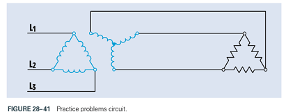
The transformer in the fig 27-17 contains one primary winding and three secondary windings.
The primary is connected to 480 V AC and contains 800 turns of wire.
One secondary has an output voltage of 320 volts and a load resistance of 12 kΩ.
Second secondary has an output voltage of 120 volts and a load resistance of 6 Ω.
Third secondary has an output voltage of 24 volts and a load impedance of 8 Ω.
The turns ratio of the first secondary can be found by dividing the smaller voltage into the larger:
The turns ratio of the first secondary is re written as,
The current flow in the first secondary can be calculated using Ohm’s law:
The amount of primary current needed to supply this secondary winding can be found using the turns ratio. As this primary has less voltage, it requires more current:
The number of turns of wire in the first secondary winding is found using the turns ratio. Because this secondary has a higher voltage than the primary, it must have more turns of wire:
The turns ratio of the second secondary winding is found by dividing the higher voltage by the lower:
The turns ratio of the second secondary is re written as,
The amount of current flow in this secondary can be determined using Ohm’s law:
The amount of primary current needed to supply this secondary winding can be found using the turns ratio. As this primary has more voltage, it requires less current:
Because the voltage of this secondary is lesser than the primary, it has less turns of wire than the primary. The number of turns of this secondary is found using the turns ratio:
The turns ratio of the third secondary winding is calculated in the same way as the other two. The larger voltage is divided by the smaller:
The turns ratio of the third secondary is re written as,
The secondary current is found using Ohm’s law:
The amount of primary current needed to supply this secondary winding can be found using the turns ratio. As this primary has more voltage, it requires less current:
Because the voltage of this secondary is lesser than the primary, it has less turns of wire than the primary. The number of turns of this third secondary is found using the turns ratio:
The primary must supply current to each of the three secondary windings. Therefore, the total amount of primary current is the sum of the currents required to supply each secondary:
Want to see more full solutions like this?
Chapter 28 Solutions
Delmar's Standard Textbook of Electricity (MindTap Course List)


- Solve only no 8, Don't use chatgpt or any , only expertarrow_forwardI need help in creating a matlab code to find the currents USING MARTIXS AND INVERSE to find the currentarrow_forwardQuestion 2 A transistor is used as a switch and the waveforms are shown in Figure 2. The parameters are Vcc = 225 V, VBE(sat) = 3 V, IB = 8 A, VCE(sat) = 2 V, Ics = 90 A, td = 0.5 µs, tr = 1 µs, ts = 3 µs, tƒ = 2 μs, and f 10 kHz. The duty cycle is k 50%. The collector- emitter leakage current is ICEO = 2 mA. Determine the power loss due to the collector current: = = = (a) during turn-on ton = td + tr VCE Vcc (b) during conduction period tn V CE(sat) 0 toff" ton Ics 0.9 Ics (c) during turn-off toff = ts + tf (d) during off-time tot (e) the total average power losses PT ICEO 0 IBS 0 Figure 2 V BE(sat) 0 主 * td tr In Is If to iB VBE T= 1/fsarrow_forward
- Question 1: The beta (B) of the bipolar transistor shown in Figure 1 varies from 12 to 60. The load resistance is Rc = 5. The dc supply voltage is VCC = 40 V and the input voltage to the base circuit is VB = 5 V. If VCE(sat) = 1.2 V, VBE(sat) = 1.6 V, and RB = 0.8 2, calculate: (a) the overdrive factor ODF. (b) the forced ẞ (c) the power loss in the transistor PT. IB VB RB + V BE RC Vcc' Ic + IE Figure 1 VCEarrow_forwardI need help in creating a matlab code to find the currentsarrow_forwardI need help fixing this MATLAB code: as I try to get it working there were some problems:arrow_forward
- I need help in construct a matlab code to find the voltage of VR1 to VR4, the currents, and the watts based on that circuit.arrow_forwardQ2: Using D flip-flops, design a synchronous counter. The counter counts in the sequence 1,3,5,7, 1,7,5,3,1,3,5,7,.... when its enable input x is equal to 1; otherwise, the counter count 0.arrow_forwardFrom the collector characteristic curves and the dc load line given below, determine the following: (a) Maximum collector current for linear operation (b) Base current at the maximum collector current (c) VCE at maximum collector current. lc (mA) 600 ΜΑ 60- 500 με 50- 400 με 40- 300 μ Α 30- Q-point 200 ΜΑ 20- 10- 100 μ Α 0 VCE (V) 1 2 3 4 5 6 7 8 9 10 [6 Paarrow_forward
- Procedure:- 1- Connect the cct. shown in fig.(2). a ADDS DS Fig.(2) 2-For resistive load, measure le output voltage by using oscilloscope ;then sketch this wave. 3- Measure the average values ::f VL and IL: 4- Repeat steps 2 & 3 but for RL load. Report:- 1- Calculate the D.C. output vcl age theoretically and compare it with the test value. 2- Calculate the harmonic cont :nts of the load voltage, and explain how filter components may be selected. 3- Compare between the three-phase half & full-wave uncontrolled bridge rectifier. 4- Draw the waveform for the c:t. shown in fig.(2) but after replaced Di and D3 by thyristors with a 30° and a2 = 90° 5- Draw the waveform for the cct. shown in fig.(2) but after replace the 6-diodes by 6- thyristor. 6- Discuss your results. Please solve No. 4 and 5arrow_forwardPlease I want solution by handwrittenarrow_forward8 00 ! Required information Consider the circuit given below. 0/2 points awarded 3 ΚΩ www t=0 6kM Scored R 1.5i Vc 1 μF 10 V If R = 5.00 kQ, determine vao+). The value of va(0) is 1.4545 V.arrow_forward
 Power System Analysis and Design (MindTap Course ...Electrical EngineeringISBN:9781305632134Author:J. Duncan Glover, Thomas Overbye, Mulukutla S. SarmaPublisher:Cengage Learning