A filter is a circuit designed to pass AC signals in some frequency range and to attenuate others. Common filters include low-pass filters , which allow low-frequency signals to pass but attenuate high frequencies; high-pass filters , which do the opposite; and band-pass filters, which pass a range of frequencies while attenuating signals with frequencies outside the band. Filters are widely used in electronics. Applications include tone and equalizer controls in audio equipment; filters to separate nearby frequencies at cell phone towers; and filters to eliminate unwanted electrical noise in biomedical instruments such as electrocardiographs. A simple design for an RC filter is shown in Fig. 28.27. Figure 28.27 An RC filter (Passage Problems 73–76) The circuit shown in Fig. 28.27 is a. a low-pass filter. b. a high-pass filter. c. a band-pass filter. d. impossible to tell without knowing the component values. in series with the output, whereas in this case it is in parallel.
A filter is a circuit designed to pass AC signals in some frequency range and to attenuate others. Common filters include low-pass filters , which allow low-frequency signals to pass but attenuate high frequencies; high-pass filters , which do the opposite; and band-pass filters, which pass a range of frequencies while attenuating signals with frequencies outside the band. Filters are widely used in electronics. Applications include tone and equalizer controls in audio equipment; filters to separate nearby frequencies at cell phone towers; and filters to eliminate unwanted electrical noise in biomedical instruments such as electrocardiographs. A simple design for an RC filter is shown in Fig. 28.27. Figure 28.27 An RC filter (Passage Problems 73–76) The circuit shown in Fig. 28.27 is a. a low-pass filter. b. a high-pass filter. c. a band-pass filter. d. impossible to tell without knowing the component values. in series with the output, whereas in this case it is in parallel.
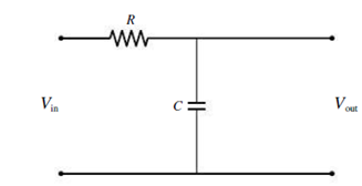
A filter is a circuit designed to pass AC signals in some frequency range and to attenuate others. Common filters include low-pass filters, which allow low-frequency signals to pass but attenuate high frequencies; high-pass filters, which do the opposite; and band-pass filters, which pass a range of frequencies while attenuating signals with frequencies outside the band. Filters are widely used in electronics. Applications include tone and equalizer controls in audio equipment; filters to separate nearby frequencies at cell phone towers; and filters to eliminate unwanted electrical noise in biomedical instruments such as electrocardiographs. A simple design for an RC filter is shown in Fig. 28.27.
Figure 28.27 An RC filter (Passage Problems 73–76)
The circuit shown in Fig. 28.27 is
a. a low-pass filter.
b. a high-pass filter.
c. a band-pass filter.
d. impossible to tell without knowing the component values.
in series with the output, whereas in this case it is in parallel.
A pendulum has a 0.4-m-long cord and is given a tangential velocity of 0.2 m/s toward the
vertical from a position 0 = 0.3 rad.
Part A
Determine the equation which describes the angular motion.
Express your answer in terms of the variable t. Express coefficients in radians to three significant figures.
ΜΕ ΑΣΦ
vec
(t)=0.3 cos (4.95t) + 0.101 sin (4.95t)
Submit Previous Answers Request Answer
× Incorrect; Try Again; 6 attempts remaining
Part A
■Review
The uniform 150-lb stone (rectangular block) is being turned over on its side by pulling the
vertical cable slowly upward until the stone begins to tip.
(Figure 1)
If it then falls freely (T = 0) from an essentially balanced at-rest position, determine the speed at which the corner A strikes the pad at B. The stone does not slip at its corner C as it falls. Suppose that height of the stone is
L = 1.2 ft.
Express your answer to three significant figures and include the appropriate units.
?
ft
VA 10.76
S
Submit Previous Answers Request Answer
× Incorrect; Try Again; 6 attempts remaining
Consider the circuit shown in the figure. The battery has emf ε = 69 volts and negligible internal resistance. The inductance is L = 0.4 H and the resistances are R 1 = 12 Ω and R 2 = 9.0 Ω. Initially the switch S is open and no currents flow. Then the switch is closed. After leaving the switch closed for a very long time, it is opened again. Just after it is opened, what is the current in R 1?
Need a deep-dive on the concept behind this application? Look no further. Learn more about this topic, physics and related others by exploring similar questions and additional content below.


 Physics for Scientists and Engineers: Foundations...PhysicsISBN:9781133939146Author:Katz, Debora M.Publisher:Cengage Learning
 College PhysicsPhysicsISBN:9781305952300Author:Raymond A. Serway, Chris VuillePublisher:Cengage Learning
 Physics for Scientists and Engineers, Technology ...PhysicsISBN:9781305116399Author:Raymond A. Serway, John W. JewettPublisher:Cengage Learning
 Physics for Scientists and EngineersPhysicsISBN:9781337553278Author:Raymond A. Serway, John W. JewettPublisher:Cengage Learning
 Physics for Scientists and Engineers with Modern ...PhysicsISBN:9781337553292Author:Raymond A. Serway, John W. JewettPublisher:Cengage Learning