Videos
(a)
The current in each resistor.
(a)
Answer to Problem 30P
The current across
Explanation of Solution
The circuit diagram is shown in figure (1).
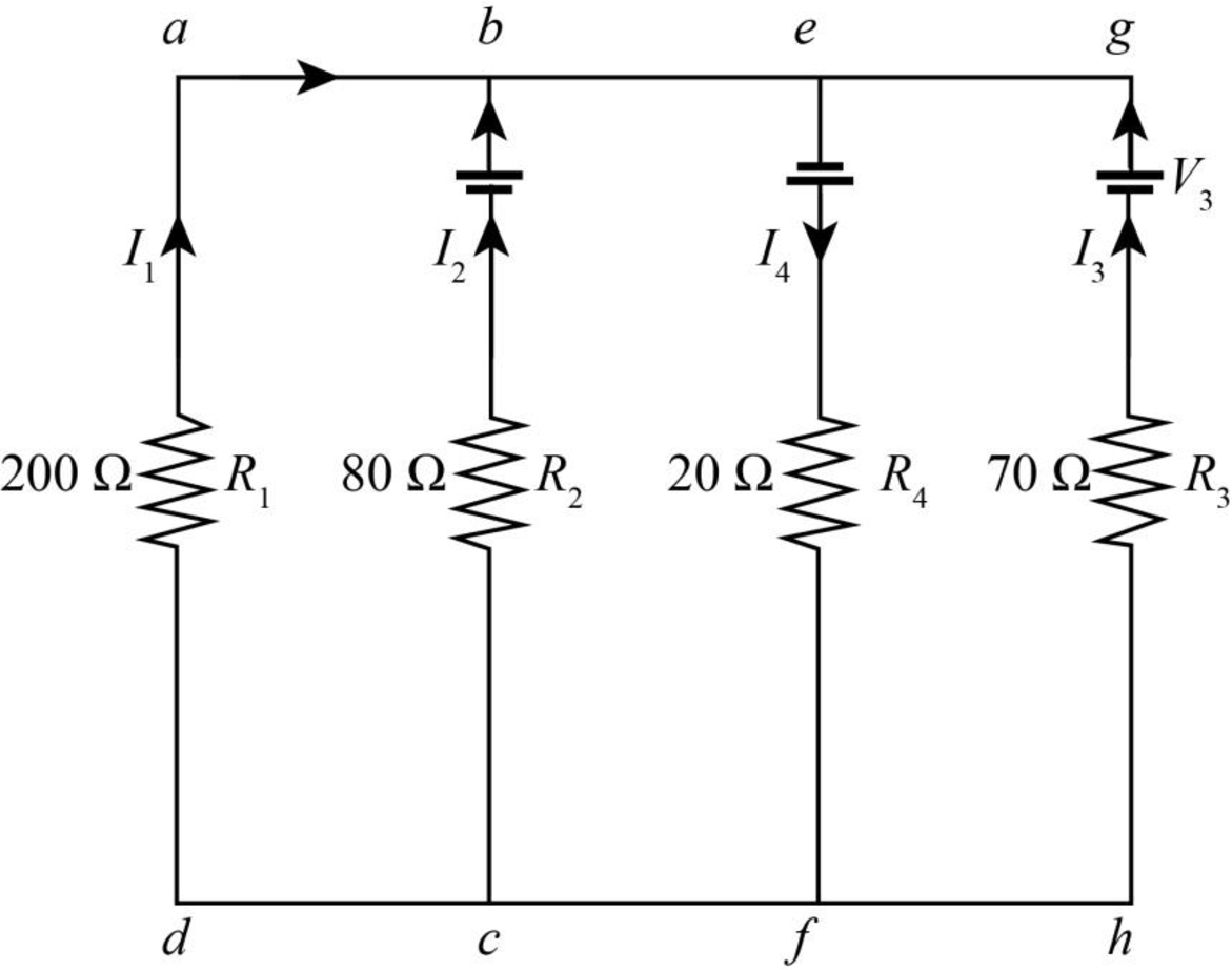
Figure-(1)
Write the expression for Kirchhoff’s voltage rule to the loop
Write the expression for Kirchhoff’s voltage rule to the loop
Write the expression for Kirchhoff’s rule for the loop
Write the expression for Kirchhoff’s rule for the circuit.
Conclusion:
Substitute
Substitute
Substitute
Substitute
Substitute
Substitute
Substitute
Substitute
Substitute
Substitute
Substitute
Therefore, the current across
(b)
The potential difference across the
(b)
Answer to Problem 30P
The potential difference across
Explanation of Solution
Write the expression for potential difference across the resistor.
Here,
Conclusion:
Substitute
Therefore, the potential difference across
Want to see more full solutions like this?
Chapter 28 Solutions
Physics For Scientists And Engineers With Modern Physics, 9th Edition, The Ohio State University


- A golf ball is struck with a velocity of 20 m/s at point A as shown below (Figure 4). (a) Determine the distance "d" and the time of flight from A to B; (b) Determine the magnitude and the direction of the speed at which the ball strikes the ground at B. 10° V₁ = 20m/s 35º Figure 4 d Barrow_forwardThe rectangular loop of wire shown in the figure (Figure 1) has a mass of 0.18 g per centimeter of length and is pivoted about side ab on a frictionless axis. The current in the wire is 8.5 A in the direction shown. Find the magnitude of the magnetic field parallel to the y-axis that will cause the loop to swing up until its plane makes an angle of 30.0 ∘ with the yz-plane. Find the direction of the magnetic field parallel to the y-axis that will cause the loop to swing up until its plane makes an angle of 30.0 ∘ with the yz-plane.arrow_forwardA particle with a charge of − 5.20 nC is moving in a uniform magnetic field of (B→=−( 1.22 T )k^. The magnetic force on the particle is measured to be (F→=−( 3.50×10⁻⁷ N )i^+( 7.60×10⁻⁷ N )j^. Calculate the y and z component of the velocity of the particle.arrow_forward
- Pls help ASAParrow_forwardPls help ASAParrow_forward9. When an electron moves into a uniform and perpendicular magnetic field, it will.. a. Accelerate parallel to the magnetic Field until it leaves b. Accelerate in a circular path c. Accelerate perpendicular to both the magnetic field and its original direction d. Repel back into the electric field 10. If a proton at rest is placed in a uniform magnetic field with no electric or gravitational field around, the proton will…….. a. Accelerate in the direction of the magnetic field b. Accelerate in a direction perpendicular to the magnetic field c. Move in a circular path d. Not acceleratearrow_forward
 Physics for Scientists and Engineers: Foundations...PhysicsISBN:9781133939146Author:Katz, Debora M.Publisher:Cengage Learning
 Principles of Physics: A Calculus-Based TextPhysicsISBN:9781133104261Author:Raymond A. Serway, John W. JewettPublisher:Cengage Learning
 Physics for Scientists and EngineersPhysicsISBN:9781337553278Author:Raymond A. Serway, John W. JewettPublisher:Cengage Learning
 Physics for Scientists and Engineers with Modern ...PhysicsISBN:9781337553292Author:Raymond A. Serway, John W. JewettPublisher:Cengage Learning
 Physics for Scientists and Engineers, Technology ...PhysicsISBN:9781305116399Author:Raymond A. Serway, John W. JewettPublisher:Cengage Learning
 College PhysicsPhysicsISBN:9781305952300Author:Raymond A. Serway, Chris VuillePublisher:Cengage Learning