
Concept explainers
Videos
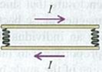
DATA A pair of long, rigid metal rods, each of length 0.50 m, lie parallel to each other on a frictionless table. Their ends are connected by identical, very lightweight
Figure P28.78
Want to see the full answer?
Check out a sample textbook solution
Chapter 28 Solutions
University Physics with Modern Physics (14th Edition)
Additional Science Textbook Solutions
Essential University Physics: Volume 2 (3rd Edition)
College Physics: A Strategic Approach (3rd Edition)
Conceptual Physical Science (6th Edition)
University Physics Volume 1
Lecture- Tutorials for Introductory Astronomy
Physics: Principles with Applications


- A portion of a long, cylindrical coaxial cable is shown in the figure below. An electrical current I = 3.0 amps flows down the center conductor, and this same current is returned in the outer conductor. Assume the current is distributed uniformly over the cross sections of the two parts of the cable. The values of the radii in the figure are r1 = 1.5 mm, r2 = 4.0 mm, and r3 = 7.0 mm. Using Ampere’s Law, find the magnitude of the magnetic field at the following distances from the center of the inner wire: a. 1.0 mm. b. 3.0 mm. c. 5.5 mm. d. 9.0 mm.arrow_forwardE13P5arrow_forward6.0 A current flows through a 5.0 m thin and straightconductor wire. What is the magnitude of themagnetic field (in unit of nT) at a distance above4.0 m from the midpoint of the wire.(Take µ0 =4πx10−7 T.m/A )arrow_forward
- I need the answer as soon as possiblearrow_forwardThe figure below is a cross-sectional view of a coaxial cable. The center conductor is surrounded by a rubber layer, an outer conductor, and another rubber layer. In a particular application, the current in the inner conductor is I1 = 1.06 A out of the page and the current in the outer conductor is I2 = 2.84 A into the page. Assuming the distance d = 1.00 mm, answer the following. a) Determine the magnitude and direction of the magnetic field at point a. b) Determine the magnitude and direction of the magnetic field at point b. Note: See image for the orignal question and figurearrow_forwardA6. A 2 cm*2 cm square loop with resistance of 0.02 2 has one edge of the loop parallel to a long straight wire. The new edge of the loop is 1 cm from the wire. If the current in the sire is increasing at 50 A/s. What is the current in the loop?arrow_forward
- 90. Figure P28.90 shows two square loops of wire. The loop on the right is fixed in place, and the one on the left is free to pivot in any direction. Both loops carry a current that is counterclock- wise when viewed from above. (a) What is the direction of the magnetic field created by the right loop at the left loop? (b) What is the initial direction of the magnetic dipole moment of the left loop? (c) How does the left loop rotate? (d) After the left loop is allowed to rotate and the system reaches equilibrium, are the magnetic dipole moments of the two loops parallel, antiparallel, or neither? Figure P28.90 free to rotate fixedarrow_forwardMagnetic resonance imaging needs a magnetic field strength of 1.5 T. The solenoid is 1.8 m long and 75 cm in diameter. It is tightly wound with a single layer of 2.50-mm-diameter superconducting wire. What is the current needed?arrow_forwardplease double check and answer it correctly. i don't want to waste money.arrow_forward
- A 8.80-μC charge is moving with a speed of 6.50 x 10⁴ m/s parallel to a very long, straight wire. The wire is 5.50 cm from the charge and carries a current of 71.0 A. Find the magnitude of the force on the charge.arrow_forwardE13P5arrow_forwardThe three conducting rings in the figure are all in the same plane as a long wire. The wire has a current / that is steadily decreasing with time at a constant rate. What can you say about the induced electromotive force in each of the rings A, B, and C? A O No electromotive force is induced in any of the rings. O A counter-clockwise electromotive force is induced in ring A, but a clockwise electromotive force is induced in rings B and C. O A clockwise electromotive force is induced in ring A. Ring B has no induced electromotive force, and ring C has a counterclockwise electromotive force. O All rings have a counterclockwise induced electromotive force. O A counter-clockwise electromotive force is induced in ring A. Ring B has no induced electromotive force, and ring C has a clockwise electromotive force.arrow_forward
 Principles of Physics: A Calculus-Based TextPhysicsISBN:9781133104261Author:Raymond A. Serway, John W. JewettPublisher:Cengage Learning
 Physics for Scientists and Engineers: Foundations...PhysicsISBN:9781133939146Author:Katz, Debora M.Publisher:Cengage Learning
 Glencoe Physics: Principles and Problems, Student...PhysicsISBN:9780078807213Author:Paul W. ZitzewitzPublisher:Glencoe/McGraw-Hill
 An Introduction to Physical SciencePhysicsISBN:9781305079137Author:James Shipman, Jerry D. Wilson, Charles A. Higgins, Omar TorresPublisher:Cengage Learning