
Physics for Scientists and Engineers
10th Edition
ISBN: 9781337553278
Author: Raymond A. Serway, John W. Jewett
Publisher: Cengage Learning
expand_more
expand_more
format_list_bulleted
Videos
Textbook Question
Chapter 27.2, Problem 27.2QQ
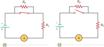
With the switch in the circuit of Figure 27.4a closed, there is no current in R2 because the current has an alternate zero-resistance path through the switch. There is current in R1, and this current is measured with the ammeter (a device for measuring current) at the bottom of the circuit. If the switch is opened (Fig. 27.4b), there is current in R2. What happens to the reading on the ammeter when the switch is opened? (a) The reading goes up. (b) The reading goes down. (c) The reading does not change.
Figure 27.4 (Quick Quiz 27.2) What happens when the switch is opened?
Expert Solution & Answer

Trending nowThis is a popular solution!

Students have asked these similar questions
Two blocks, A and B (with mass 45 kg and 120 kg, respectively), are connected by a string, as shown in the figure below. The pulley is frictionless and of negligible mass. The coefficient of kinetic friction between block A and the incline is μk = 0.26. Determine the change in the kinetic
energy of block A as it moves from to ①, a distance of 15 m up the incline (and block B drops downward a distance of 15 m) if the system starts from rest.
]
37°
A
©
B
A skateboarder with his board can be modeled as a particle of mass 80.0 kg, located at his center of mass. As shown in the figure below, the skateboarder starts from rest in a crouching position at one lip of a half-pipe (point). On his descent, the skateboarder moves without friction so
that his center of mass moves through one quarter of a circle of radius 6.20 m.
i
(a) Find his speed at the bottom of the half-pipe (point Ⓡ).
m/s
(b) Immediately after passing point Ⓑ, he stands up and raises his arms, lifting his center of mass and essentially "pumping" energy into the system. Next, the skateboarder glides upward with his center of mass moving in a quarter circle of radius 5.71 m, reaching point D. As he
passes through point ①, the speed of the skateboarder is 5.37 m/s. How much chemical potential energy in the body of the skateboarder was converted to mechanical energy when he stood up at point Ⓑ?
]
(c) How high above point ① does he rise?
m
A 31.0-kg child on a 3.00-m-long swing is released from rest when the ropes of the swing make an angle of 29.0° with the vertical.
(a) Neglecting friction, find the child's speed at the lowest position.
m/s
(b) If the actual speed of the child at the lowest position is 2.40 m/s, what is the mechanical energy lost due to friction?
]
Chapter 27 Solutions
Physics for Scientists and Engineers
Ch. 27.1 - To maximize the percentage of the power from the...Ch. 27.2 - With the switch in the circuit of Figure 27.4a...Ch. 27.2 - With the switch in the circuit of Figure 27.6a...Ch. 27.2 - Prob. 27.4QQCh. 27.4 - Consider the circuit in Figure 27.17 and assume...Ch. 27 - Two 1.50-V batterieswith their positive terminals...Ch. 27 - As in Example 27.2, consider a power supply with...Ch. 27 - Figure P27.3 shows the interior of a three-way...Ch. 27 - Prob. 4PCh. 27 - Consider the two circuits shown in Figure P27.5 in...
Ch. 27 - Consider strings of incandescent lights that are...Ch. 27 - You are working at an electronics fabrication...Ch. 27 - In your new job at an engineering company, your...Ch. 27 - A battery with = 6.00 V and no internal...Ch. 27 - A battery with emf and no internal resistance...Ch. 27 - Todays class on current and resistance is about to...Ch. 27 - Why is the following situation impossible? A...Ch. 27 - Calculate the power delivered to each resistor in...Ch. 27 - For the purpose of measuring the electric...Ch. 27 - Four resistors are connected to a battery as shown...Ch. 27 - You have a faculty position at a community college...Ch. 27 - The circuit shown in Figure P27.17 is connected...Ch. 27 - The following equations describe an electric...Ch. 27 - Taking R = 1.00 k and = 250 V in Figure P27.19,...Ch. 27 - In the circuit of Figure P27.20, the current I1 =...Ch. 27 - (a) Can the circuit shown in Figure P27.21 be...Ch. 27 - For the circuit shown in Figure P27.22, we wish to...Ch. 27 - An uncharged capacitor and a resistor are...Ch. 27 - Show that the time constant in Equation 27.20 has...Ch. 27 - In the circuit of Figure P27.25, the switch S has...Ch. 27 - In the circuit of Figure P27.25, the switch S has...Ch. 27 - A 10.0-F capacitor is charged by a 10.0-V battery...Ch. 27 - Show that the integral 0e2t/RCdtin Example 27.11...Ch. 27 - You and your roommates are studying hard for your...Ch. 27 - Prob. 30PCh. 27 - Turn on your desk lamp. Pick up the cord, with...Ch. 27 - Four resistors are connected in parallel across a...Ch. 27 - Find the equivalent resistance between points a...Ch. 27 - The circuit in Figure P27.34a consists of three...Ch. 27 - The circuit in Figure P27.35 has been connected...Ch. 27 - The resistance between terminals a and b in Figure...Ch. 27 - (a) Calculate the potential difference between...Ch. 27 - Why is the following situation impossible? A...Ch. 27 - When two unknown resistors are connected in series...Ch. 27 - When two unknown resistors are connected in series...Ch. 27 - The circuit in Figure P27.41 contains two...Ch. 27 - Two resistors R1 and R2 are in parallel with each...Ch. 27 - A power supply has an open-circuit voltage of 40.0...Ch. 27 - A battery is used to charge a capacitor through a...Ch. 27 - An ideal voltmeter connected across a certain...Ch. 27 - (a) Determine the equilibrium charge on the...Ch. 27 - In Figure P27.47, suppose the switch has been...Ch. 27 - Figure P27.48 shows a circuit model for the...Ch. 27 - The student engineer of a campus radio station...Ch. 27 - A voltage V is applied to a series configuration...Ch. 27 - The switch in Figure P27.51a closes when Vc23Vand...
Knowledge Booster


Learn more about
Need a deep-dive on the concept behind this application? Look no further. Learn more about this topic, physics and related others by exploring similar questions and additional content below.Similar questions
- A force acting on a particle moving in the xy plane is given by F = (2yî + x²), where F is in newtons and x and y are in meters. The particle moves from the origin to a final position having coordinates x = 5.60 m and y = 5.60 m, as shown in the figure below. y (m) B (x, y) x (m) (a) Calculate the work done by F on the particle as it moves along the purple path (0 Ⓐ©). ] (b) Calculate the work done by ♬ on the particle as it moves along the red path (0 BC). J (c) Is F conservative or nonconservative? ○ conservative nonconservativearrow_forwardA 3.5-kg block is pushed 2.9 m up a vertical wall with constant speed by a constant force of magnitude F applied at an angle of 0 = 30° with the horizontal, as shown in the figure below. If the coefficient of kinetic friction between block and wall is 0.30, determine the following. (a) the work done by F J (b) the work done by the force of gravity ] (c) the work done by the normal force between block and wall J (d) By how much does the gravitational potential energy increase during the block's motion? ]arrow_forwardPhysics different from a sea breeze from a land breezearrow_forward
- File Preview Design a capacitor for a special purpose. After graduating from medical school you and a friend take a three hour cruise to celebrate and end up stranded on an island. While looking for food, a spider falls on your friend giving them a heart attack. Recalling your physics, you realize you can build a make-shift defibrillator by constructing a capacitor from materials on the boat and charging it using the boat's battery. You know that the capacitor must hold 100 J of energy and be at 1000 V (fortunately this is an electric boat which has batteries that are 1000 V) to work. You decide to construct the capacitor by tightly sandwiching a single layer of Saran wrap between sheets of aluminum foil. You read the Saran wrap box and fortunately they tell you that it has a thickness 0.01 mm and dielectric constant of 2.3. The Saran wrap and foil are 40 cm wide and very long. How long is the final capacitor you build that saves your friend?arrow_forwardHow do I plot the force F in Matlba (of gravity pulling on the masses) versus spring displacement, and fit the data with a linear function to find the value for the spring constant. To get a linear fit, use polynomial order 1. Report the value of 'k' from the fit. What code is used?arrow_forwardOk im confused on this portion of the questions being asked. the first snip is the solution you gave which is correct. BUt now it is asking for this and im confused. The magnitude of the force F_11 is __________LB. The direction of the force F_11 is __________LB.arrow_forward
- Solve and answer the problem correctly and be sure to check your work. Thank you!!arrow_forwardThe spring in the figure has a spring constant of 1300 N/m. It is compressed 17.0 cm, then launches a 200 g block. The horizontal surface is frictionless, but the block’s coefficient of kinetic friction on the incline is 0.200. What distance d does the block sail through the air?arrow_forwardSolve and answer the problem correctly and be sure to check your work. Thank you!!arrow_forward
arrow_back_ios
SEE MORE QUESTIONS
arrow_forward_ios
Recommended textbooks for you
 Physics for Scientists and Engineers with Modern ...PhysicsISBN:9781337553292Author:Raymond A. Serway, John W. JewettPublisher:Cengage Learning
 Physics for Scientists and EngineersPhysicsISBN:9781337553278Author:Raymond A. Serway, John W. JewettPublisher:Cengage Learning
 Physics for Scientists and Engineers, Technology ...PhysicsISBN:9781305116399Author:Raymond A. Serway, John W. JewettPublisher:Cengage Learning
 College PhysicsPhysicsISBN:9781938168000Author:Paul Peter Urone, Roger HinrichsPublisher:OpenStax College
 Principles of Physics: A Calculus-Based TextPhysicsISBN:9781133104261Author:Raymond A. Serway, John W. JewettPublisher:Cengage Learning
 Physics for Scientists and Engineers: Foundations...PhysicsISBN:9781133939146Author:Katz, Debora M.Publisher:Cengage Learning
Physics for Scientists and Engineers with Modern ...
Physics
ISBN:9781337553292
Author:Raymond A. Serway, John W. Jewett
Publisher:Cengage Learning
Physics for Scientists and Engineers
Physics
ISBN:9781337553278
Author:Raymond A. Serway, John W. Jewett
Publisher:Cengage Learning
Physics for Scientists and Engineers, Technology ...
Physics
ISBN:9781305116399
Author:Raymond A. Serway, John W. Jewett
Publisher:Cengage Learning
College Physics
Physics
ISBN:9781938168000
Author:Paul Peter Urone, Roger Hinrichs
Publisher:OpenStax College
Principles of Physics: A Calculus-Based Text
Physics
ISBN:9781133104261
Author:Raymond A. Serway, John W. Jewett
Publisher:Cengage Learning
Physics for Scientists and Engineers: Foundations...
Physics
ISBN:9781133939146
Author:Katz, Debora M.
Publisher:Cengage Learning
What is Electromagnetic Induction? | Faraday's Laws and Lenz Law | iKen | iKen Edu | iKen App; Author: Iken Edu;https://www.youtube.com/watch?v=3HyORmBip-w;License: Standard YouTube License, CC-BY