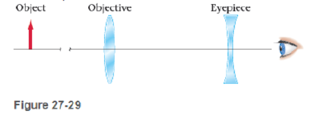
Problem 1CQ Problem 2CQ Problem 3CQ: If your near-point distance is N, how close can you stand to a mirror and still be able to focus on... Problem 4CQ: When you open your eyes underwater, everything looks blurry. Can this be thought of as an extreme... Problem 5CQ: When you use a simple magnifying glass, does it matter whether you hold the object to be examined... Problem 6CQ: Does chromatic aberration occur in mirrors? Explain. Problem 1PCE: BIO Predict/Explain Octopus Eyes To focus its eyes, an octopus does not change the shape of its... Problem 2PCE: Your friend is 1.7 m tall. (a) When she stands 3.2 m from you, what is the height of her image... Problem 3PCE: Which forms the larger image on the retina of your eye a 43-ft tree seen from a distance of 210 ft,... Problem 4PCE: Approximating the eye as a single thin lens 2.70 cm from the retina, find the eyes near-point... Problem 5PCE: Approximating the eye as a single thin lens 2.70 cm from the retina, find the focal length of the... Problem 6PCE: Find the far-point distance of a person whose relaxed eye has a focal length of 2.68 cm, treating... Problem 7PCE: Four camera lenses have the following focal lengths and /-numbers Lens Focal length (mm) f-number A... Problem 8PCE: BIO The focal length of the human eye is approximately 1.7 cm. (a) What is the f -number for the... Problem 9PCE: Predict/Calculate A camera with a 65-mm-focal-length lens has aperture f -numbers of 2.8, 4, 8, 11... Problem 10PCE: The actual light sensor size of a digital camera is 14.9 mm 22.3 mm. You want to take a photo of... Problem 11PCE: (a) Find the f -number of a telescope with an objective diameter of 8 3 cm and a focal length of 91... Problem 12PCE: You are taking a photo of a poster on the wall of your dorm room, so you cant back away any farther... Problem 13PCE: You are taking pictures of the beach at sunset Just before the Sun sets, a shutter speed of 1/100... Problem 14PCE: Predict/Calculate You are taking a photograph of a horse race. A shutter speed of 125 at f/5.6... Problem 15PCE: The Hale Telescope The 200-in. (5.08-m) diameter mirror of the Hale telescope on Mount Palomar has a... Problem 16PCE: Predict/Explain Two professors are stranded on a deserted island. Both wear glasses though one is... Problem 17PCE: A clerk at the local grocery store wears glasses that make her eyes look larger than they actually... Problem 18PCE: The umpire at a baseball game wears glasses that make his eyes look smaller than they actually are.... Problem 19PCE: A police detective discovers eyeglasses with a focal length of 80.0 cm at a crime scene. (a) if the... Problem 20PCE: BIO The cornea of a normal human eye has an optical power of +44.0 diopters. What is its focal... Problem 21PCE: A myopic student is shaving without his glasses. If his eyes have a far point of 1.9 m, what is the... Problem 22PCE: An eyeglass prescription calls for a lens with an optical power of +2.9 diopters. What is the focal... Problem 23PCE: An optometrist prescribes contact lenses with a power of 0.75 diopter for you. What is your far-... Problem 24PCE: Two thin lenses, with f1 = +25.0 cm and f2 = 42.5 cm are placed in contact. What is the local length... Problem 25PCE: Two concave lenses, each with f = 15 cm, are separated by 7.5 cm. An object is placed 25 cm in front... Problem 26PCE: BIO Predict/Calculate The focal length of a relaxed human eye is approximately 1.7 cm. When we focus... Problem 27PCE: BIO Predict/Calculate Diopter Change in Diving Cormorants Double-crested cormorants (Phalacrocorax... Problem 28PCE: A converging lens of focal length 9,000 cm is 18.0 cm to the left of a diverging lens of focal... Problem 29PCE: Repeat Problem 28, this time with the coin placed 18.0 cm to the right of the diverging lens. Problem 30PCE: Find the focal length of contact lenses that would allow a farsighted person with a near-point... Problem 31PCE: Find the focal length of contact lenses that would allow a nearsighted person with a 125-cm far. Problem 32PCE: What focal length should a pair of contact lenses have if they are to correct the vision of a person... Problem 33PCE: Reading glasses with a power of + 1.50 diopters make reading a book comfortable for you when you... Problem 34PCE: A nearsighted person wears contacts with a focal length of 8.5 cm. If this persons far-point... Problem 35PCE: Without his glasses, Isaac can see objects clearly only if they are less than 3.8 m from his eyes.... Problem 36PCE: A person whose near-point distance is 42.5 cm wears a pair of glasses that are 2.1 cm from her eyes.... Problem 37PCE: A pair of eyeglasses is designed to allow a person with a far-point distance of 2.50 m to read a... Problem 38PCE: Predict/Calculate Your favorite aunt can read a newspaper only if it is within 15.0 cm of her eyes.... Problem 39PCE: Predict/Calculate The relaxed eyes of a patient have a refractive power of 48.5 diopters. (a) Is... Problem 40PCE: Without glasses, your Uncle Albert can see things clearly only if they are between 35 cm and 160 cm... Problem 41PCE: A 2.05-cm-tall object is placed 30.0 cm to the left of a converging lens with a focal length f1 =... Problem 42PCE: A simple camera telephoto lens consists of two lenses. The objective lens has a focal length f1 =... Problem 43PCE: Predict/Calculate With unaided vision, a librarian can focus only on objects that lie at distances... Problem 44PCE: A persons prescription for her new bifocal glasses calls for a refractive power of 0 445 diopter in... Problem 45PCE: A persons prescription for his new bifocal eyeglasses calls for a refractive power of 0.0625 diopter... Problem 46PCE: Two lenses, with f1 = +20.0 cm and f2 = +30.0 cm, are placed on the x axis, as shown in Figure 27-28... Problem 47PCE: A converging lens with a focal length of 4.0 cm is to the left of a second identical lens. When a... Problem 48PCE: Two magnifying glasses are for sale at a store. Magnifying glass 1 has a 4-in. diameter with a long... Problem 49PCE: The Moon is 3476 km in diameter and orbits the Earth at an average distance of 384,400 km. (a) What... Problem 50PCE: A magnifying glass is a single convex lens with a focal length of f = +14 0 cm. (a) What is the... Problem 51PCE: Calculate the focal length of a magnifying lens designed to produce an angular magnification of 8.50... Problem 52PCE: Predict/Calculate A student has two lenses, one of focal length f1 = 5.0 cm and the other with focal... Problem 53PCE: A beetle 4.93 mm long is examined with a simple magnifier of focal length f= 10.1 cm. If the... Problem 54PCE: To engrave wishes of good luck on a watch, an engraver uses a magnifier whose focal length is 8.75... Problem 55PCE: A jeweler examines a diamond with a magnifying glass. If the near-point distance of the jeweler is... Problem 56PCE: In Problem 55, find the angular magnification when the diamond is held 5.59 cm from the magnifying... Problem 57PCE Problem 58PCE: You have two lenses: lens 1 with a focal length of 0.45 cm and lens 2 with a focal length of 1.9 cm.... Problem 59PCE: Predict/Calculate Microscope objective A is labeled 15 and objective B is labeled 25 (a) Which... Problem 60PCE: A compound microscope has an objective lens with a focal length of 2.2 cm and an eyepiece with a... Problem 61PCE: BIO A typical red blood cell subtends an angle of only 1.9 105 rad when viewed at a persons... Problem 62PCE: (a) If you treat a 10x eyepiece of a microscope as a magnifying glass that produces an image at... Problem 63PCE: The medium-power objective lens in a laboratory microscope has a focal length fobjective = 3.75 mm.... Problem 64PCE: A compound microscope has the objective and eyepiece mounted in a tube that is 18.0 cm long. The... Problem 65PCE: The barrel of a compound microscope is 15 cm in length. The specimen will be mounted 1.0 cm from the... Problem 66PCE: A compound microscope uses a 75.0-mm lens as the objective and a 2.0-cm lens as the eyepiece. The... Problem 67PCE: The tube length of a microscope is defined to be the difference between the (objective) image... Problem 68PCE: Two telescopes of different lengths produce the same angular magnification. Is the focal length of... Problem 69PCE: A grade school student plans to build a 35-power telescope as a science fair project. She starts... Problem 70PCE: A 75-power refracting telescope has an eyepiece with a focal length of 5.0 cm. How long is the... Problem 71PCE: An amateur astronomer wants to build a small refracting telescope. The only lenses available to him... Problem 72PCE: A pirate sights a distant ship with a spyglass that gives an angular magnification of 22. If the... Problem 73PCE: A telescope has lenses with focal lengths f1 = +30.0 cm and f2 = +5.0 cm. (a) What distance between... Problem 74PCE: Jason has a 25-power telescope whose objective lens has a focal length of 120 cm. To make his sister... Problem 75PCE: Roughing It with Science A professor shipwrecked on Hooligans Island decides to build a telescope... Problem 76PCE: Galileos Telescope Galileos first telescope used a convex objective lens and a concave eyepiece, as... Problem 77PCE: The Moon has an angular size of 0 50 when viewed with unaided vision from Earth. Suppose the Moon is... Problem 78PCE: A telescope is 275 mm long and has an objective lens with a focal length of 257 mm. (a) What is the... Problem 79PCE: The focal length for light that strikes near the center of a spherical convex lens is 15 cm.... Problem 80PCE: The focal length for red light that strikes a spherical concave lens is 15 cm. Referring to Figure... Problem 81PCE: BIO Predict/Explain Intracorneal Ring An intracorneal ring is a small plastic device implanted in a... Problem 82GP: CE BIO The lens in a normal human eye, with aqueous humor on one side and vitreous humor on the... Problem 83GP: CE BIO Predict/Explain Treating Cataracts When the lens in a persons eye becomes clouded by a... Problem 84GP: Galileos original telescope (Figure 27-29) used a convex objective and a concave eyepiece. Use a ray... Problem 85GP: Predict/Calculate For each of the following cases, use a ray diagram to show that the angular sizes... Problem 86GP: Predict/Calculate You have two lenses, with focal lengths f1= +2.60 cm and f2 = +20 4 cm. (a) How... Problem 87GP: BIO The eye is actually a multiple-lens system, but we can approximate it with a single-lens system... Problem 88GP: BIO Fitting Contact Lenses with a Keratometer When a patient is being fitted with contact lenses,... Problem 89GP: Pricey Stamp A rare 1918 Jenny stamp, depicting a misprinted, upside-down Curtiss JN-4 Jenny... Problem 90GP Problem 91GP: Consider a Galilean telescope, as illustrated in Figure 27-29, constructed from two lenses with... Problem 92GP: A farsighted person uses glasses with a refractive power of 3.6 diopters. The glasses are worn 2.5... Problem 93GP: Landing on an Aircraft Carrier The Fresnel Lens Optical Landing System (FLOLS) used to ensure safe... Problem 94GP: A Cassegrain astronomical telescope uses two mirrors to form the image. The larger (concave)... Problem 95GP: Predict/Calculate A convex Ions (f = 20.0 cm) is placed 10.0 cm in front of a piano mirror. A... Problem 96GP: The diameter of a collimated laser beam can be expanded or reduced by using two converging lenses,... Problem 97GP: Consider three lenses with focal lengths of 25.0 cm, 15.0 cm and 11.0 cm positioned on the x axis at... Problem 98GP: Because a concave lens cannot form a real image of a real object, it is difficult to measure its... Problem 99GP: A person with a near-point distance N uses a magnifying glass with a focal length f. Show that the... Problem 100GP Problem 101PP Problem 102PP Problem 103PP Problem 104PP: Predict/Calculate Referring to Example 27-4 Suppose a persons eyeglasses have a focal length of 301... Problem 105PP: Predict/Calculate Referring to Example 27-4 in Example 27-4, a person has a far- point distance of... Problem 106PP: Predict/Calculate Referring to Example 27-4 In Example 27-4 a person has a far- point distance of... Problem 107PP: Predict/Calculate Referring to Example 27-6 Suppose a persons eyeglasses have a refractive power of... Problem 108PP: Predict/Calculate Referring to Example 27-6 Suppose a persons near-point distance is 67.0 cm. (a) Is... format_list_bulleted


 Physics for Scientists and Engineers: Foundations...PhysicsISBN:9781133939146Author:Katz, Debora M.Publisher:Cengage Learning
 University Physics Volume 3PhysicsISBN:9781938168185Author:William Moebs, Jeff SannyPublisher:OpenStax
 Principles of Physics: A Calculus-Based TextPhysicsISBN:9781133104261Author:Raymond A. Serway, John W. JewettPublisher:Cengage Learning
 Glencoe Physics: Principles and Problems, Student...PhysicsISBN:9780078807213Author:Paul W. ZitzewitzPublisher:Glencoe/McGraw-Hill
 Physics for Scientists and Engineers with Modern ...PhysicsISBN:9781337553292Author:Raymond A. Serway, John W. JewettPublisher:Cengage Learning
 Physics for Scientists and EngineersPhysicsISBN:9781337553278Author:Raymond A. Serway, John W. JewettPublisher:Cengage Learning