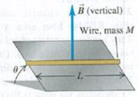
A straight piece of conducting wire with mass M and length L is placed on a frictionless incline tilted at an angle θ from the horizontal (Fig. P27.61). There is a uniform, vertical magnetic field B → at all points (produced by an arrangement of magnets not shown in the figure). To keep the wire front sliding down the incline, a voltage source is attached to the ends of the wire. When just the right amount of current flows through the wire, the wire remains at rest. Determine the magnitude and direction of the current in the wire that will cause the wire to remain at rest. Copy the figure and draw the direction of the current on your copy. In addition, show in a free-body diagram all the forces that act on the wire. Figure P27.61
A straight piece of conducting wire with mass M and length L is placed on a frictionless incline tilted at an angle θ from the horizontal (Fig. P27.61). There is a uniform, vertical magnetic field B → at all points (produced by an arrangement of magnets not shown in the figure). To keep the wire front sliding down the incline, a voltage source is attached to the ends of the wire. When just the right amount of current flows through the wire, the wire remains at rest. Determine the magnitude and direction of the current in the wire that will cause the wire to remain at rest. Copy the figure and draw the direction of the current on your copy. In addition, show in a free-body diagram all the forces that act on the wire. Figure P27.61
A straight piece of conducting wire with mass M and length L is placed on a frictionless incline tilted at an angle θ from the horizontal (Fig. P27.61). There is a uniform, vertical magnetic field
B
→
at all points (produced by an arrangement of magnets not shown in the figure). To keep the wire front sliding down the incline, a voltage source is attached to the ends of the wire. When just the right amount of current flows through the wire, the wire remains at rest. Determine the magnitude and direction of the current in the wire that will cause the wire to remain at rest. Copy the figure and draw the direction of the current on your copy. In addition, show in a free-body diagram all the forces that act on the wire.
4. In the figure below what is the value of the angle 0?
A
30
PLEASE help with the experimental setup for this theory because i am so confused.
Part 2 - Geometry and Trigonometry
1. Line B touches the circle at a single point. Line A extends radially through the center of
the circle.
A
B
(a) Which line is tangential to the circumference of the circle?
(b) What is the angle between lines A and B.
2. In the figure below what is the angle C?
30
45
3. In the figure below what is the value of the angle 0?
30°
4. In the figure below what is the value of the angle 0?
A
30°
Chapter 27 Solutions
University Physics with Modern Physics Plus Mastering Physics with eText -- Access Card Package (14th Edition)
Physics for Scientists and Engineers: A Strategic Approach, Vol. 1 (Chs 1-21) (4th Edition)
Knowledge Booster
Learn more about
Need a deep-dive on the concept behind this application? Look no further. Learn more about this topic, physics and related others by exploring similar questions and additional content below.
What is Electromagnetic Induction? | Faraday's Laws and Lenz Law | iKen | iKen Edu | iKen App; Author: Iken Edu;https://www.youtube.com/watch?v=3HyORmBip-w;License: Standard YouTube License, CC-BY


 Principles of Physics: A Calculus-Based TextPhysicsISBN:9781133104261Author:Raymond A. Serway, John W. JewettPublisher:Cengage Learning
 Physics for Scientists and Engineers: Foundations...PhysicsISBN:9781133939146Author:Katz, Debora M.Publisher:Cengage Learning
 Physics for Scientists and Engineers, Technology ...PhysicsISBN:9781305116399Author:Raymond A. Serway, John W. JewettPublisher:Cengage Learning
 College PhysicsPhysicsISBN:9781305952300Author:Raymond A. Serway, Chris VuillePublisher:Cengage Learning
 College PhysicsPhysicsISBN:9781285737027Author:Raymond A. Serway, Chris VuillePublisher:Cengage Learning
 Physics for Scientists and Engineers with Modern ...PhysicsISBN:9781337553292Author:Raymond A. Serway, John W. JewettPublisher:Cengage Learning