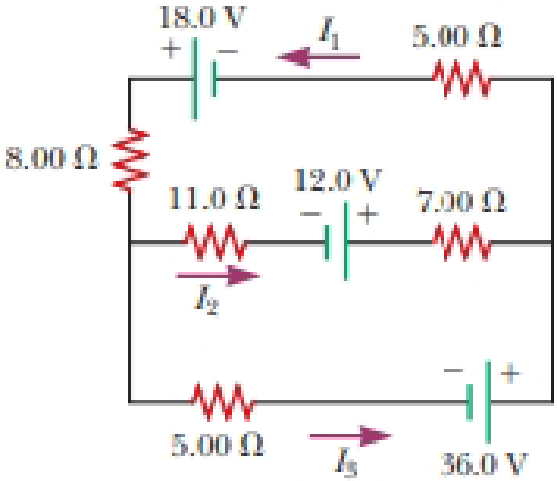
For the circuit shown in Figure P27.22, we wish to find the currents I1, I2, and I3. Use Kirchhoff’s rules to obtain equations for (a) the upper loop, (b) the lower loop, and (c) the junction on the left side. In each case, suppress units for clarity and simplify, combining the terms. (d) Solve the junction equation for I3. (e) Using the equation found in part (d), eliminate I3 from the equation found in part (b). (f) Solve the equations found in parts (a) and (e) simultaneously for the two unknowns I1 and I2. (g) Substitute the answers found in part (f) into the junction equation found in part (d), solving for I3. (h) What is the significance of the negative answer for I2?
Figure P27.22
(a)
The equation by using Kirchhoff’s rules in the upper loop.
Answer to Problem 22P
The equation by using Kirchhoff’s rules in the upper loop is
Explanation of Solution
Given info: The figure is given as,
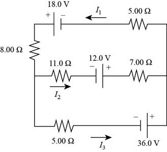
By going counterclockwise around the upper loop and suppressing the unites, the Kirchhoff’s law is applied.
The equation for the upper loop is,
Conclusion:
Therefore, the equation by using Kirchhoff’s rules in the upper loop is
(b)
The equation by using Kirchhoff’s rules in the lower loop.
Answer to Problem 22P
The equation by using Kirchhoff’s rules in the lower loop is
Explanation of Solution
Given info: The figure is given as,
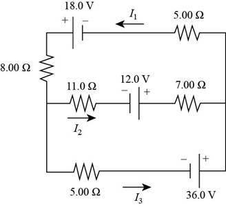
By going counterclockwise around the lower loop and suppressing the unites, the Kirchhoff’s law is applied.
The equation for the lower loop is,
Conclusion:
Therefore, the equation by using Kirchhoff’s rules in the lower loop is
(c)
The equation by using Kirchhoff’s rules at the junction on the left side.
Answer to Problem 22P
The equation by using Kirchhoff’s rules at the junction on the left side is
Explanation of Solution
Given info: The figure is given as,
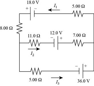
Apply the junction rule at the node in the left end of the circuit.
The equation for the junction on the left side is,
Conclusion:
Therefore, the equation by using Kirchhoff’s rules at the junction on the left side is
(d)
To solve: The junction on the left side for
Answer to Problem 22P
The junction on the left side for
Explanation of Solution
Given info: The figure is given as,
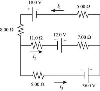
Apply the junction rule at the node in the left end of the circuit.
Rearrange the equation (3) as,
Conclusion:
Therefore, the junction on the left side for
(e)
To eliminate: The current
Answer to Problem 22P
The equation after elimination\ for
Explanation of Solution
Given info: The figure is given as,

The equation for
Substitute
Conclusion:
Therefore, the equation after elimination for
(f)
The value of
Answer to Problem 22P
The value of
Explanation of Solution
Given info: The figure is given as,
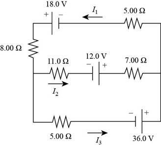
Rearrange the equation (4) for
Recall the equation (1).
Substitute
Further, solve,
Thus, the value of
Substitute
Conclusion:
Therefore, the value of
(g)
The value of
Answer to Problem 22P
The value of
Explanation of Solution
Given info: The figure is given as,

The equation for
Substitute
Conclusion:
Therefore, the value of
(h)
The significant of the negative sign of answer of
Answer to Problem 22P
The negative sign in the answer for
Explanation of Solution
Given info: The figure is given as,

The negative sign in the answer for
Conclusion:
Therefore, the negative sign in the answer for
Want to see more full solutions like this?
Chapter 27 Solutions
Bundle: Physics For Scientists And Engineers With Modern Physics, Loose-leaf Version, 10th + Webassign Printed Access Card For Serway/jewett's Physics For Scientists And Engineers, 10th, Single-term
Additional Science Textbook Solutions
Campbell Essential Biology (7th Edition)
College Physics: A Strategic Approach (3rd Edition)
Fundamentals of Physics Extended
Chemistry: Structure and Properties (2nd Edition)
Human Anatomy & Physiology (2nd Edition)
General, Organic, and Biological Chemistry - 4th edition
- A skier of mass 75 kg is pulled up a slope by a motor-driven cable. (a) How much work is required to pull him 50 m up a 30° slope (assumed frictionless) at a constant speed of 2.8 m/s? KJ (b) What power (expressed in hp) must a motor have to perform this task? hparrow_forwardA block of mass 1.4 kg is attached to a horizontal spring that has a force constant 900 N/m as shown in the figure below. The spring is compressed 2.0 cm and is then released from rest. a x = 0 x b (a) A constant friction force of 4.4 N retards the block's motion from the moment it is released. Using an energy approach, find the position x of the block at which its speed is a maximum. cm (b) Explore the effect of an increased friction force of 13.0 N. At what position of the block does its maximum speed occur in this situation? cmarrow_forwardA block of mass m = 3.00 kg situated on a rough incline at an angle of 0 = 37.0° is connected to a spring of negligible mass having a spring constant of 100 N/m (see the figure below). The pulley is frictionelss. The block is released from rest when the spring is unstretched. The block moves 11.0 cm down the incline before coming to rest. Find the coefficient of kinetic friction between block and incline. k=100 N/m Ө marrow_forward
- 23. What is the velocity of a beam of electrons that goes undeflected when passing through perpendicular electric and magnetic fields of magnitude 8.8 X 10³ V/m and 7.5 X 10⁻³ T. respectively? What is the radius of the electron orbit if the electric field is turned off?arrow_forward10. A light bulb emits 25.00 W of power as visible light. What are the average electric and magnetic fields from the light at a distance of 2.0 m?arrow_forward9. Some 1800 years ago Roman soldiers effectively used slings as deadly weapons. The length of these slings averaged about 81 cm and the lead shot that they used weighed about 30 grams. If in the wind up to a release, the shot rotated around the Roman slinger with a period of .15 seconds. Find the maximum acceleration of the shot before being released in m/s^2 and report it to two significant figures.arrow_forward
- In the movie Fast X, a 10100 kg round bomb is set rolling in Rome. The bomb gets up to 17.6 m/s. To try to stop the bomb, the protagonist Dom swings the counterweight of a crane, which has a mass of 354000 kg into the bomb at 3.61 m/s in the opposite direction. Directly after the collision the crane counterweight continues in the same direction it was going at 2.13 m/s. What is the velocity (magnitude and direction) of the bomb right after the collision?arrow_forwardDon't use aiarrow_forwardMake sure to draw a sketch with scale pleasearrow_forward

 Principles of Physics: A Calculus-Based TextPhysicsISBN:9781133104261Author:Raymond A. Serway, John W. JewettPublisher:Cengage Learning
 Physics for Scientists and Engineers: Foundations...PhysicsISBN:9781133939146Author:Katz, Debora M.Publisher:Cengage Learning
 College PhysicsPhysicsISBN:9781305952300Author:Raymond A. Serway, Chris VuillePublisher:Cengage Learning
 College PhysicsPhysicsISBN:9781285737027Author:Raymond A. Serway, Chris VuillePublisher:Cengage Learning
 Physics for Scientists and Engineers, Technology ...PhysicsISBN:9781305116399Author:Raymond A. Serway, John W. JewettPublisher:Cengage Learning


