The Wheatstone Bridge. The circuit shown in Fig. P26.74 , called a Wheatstone bridge , is used to determine the value of an unknown resistor X by comparison with three resistors M , N , and P whose resistances can be varied. For each setting, the resistance of each resistor is precisely known. With switches S 1 and S 2 closed, these resistors are varied until the current in the galvanometer G is zero; the bridge is then said to be balanced . (a) Show that under this condition the unknown resistance is given by X = MP / N . (This method permits very high precision in comparing resistors.) (b) If galvanometer G shows zero deflection when M = 850.0 Ω, N = 15.00 Ω, and P = 33.48 Ω, what is the unknown resistance X ? Figure P26.74
The Wheatstone Bridge. The circuit shown in Fig. P26.74 , called a Wheatstone bridge , is used to determine the value of an unknown resistor X by comparison with three resistors M , N , and P whose resistances can be varied. For each setting, the resistance of each resistor is precisely known. With switches S 1 and S 2 closed, these resistors are varied until the current in the galvanometer G is zero; the bridge is then said to be balanced . (a) Show that under this condition the unknown resistance is given by X = MP / N . (This method permits very high precision in comparing resistors.) (b) If galvanometer G shows zero deflection when M = 850.0 Ω, N = 15.00 Ω, and P = 33.48 Ω, what is the unknown resistance X ? Figure P26.74
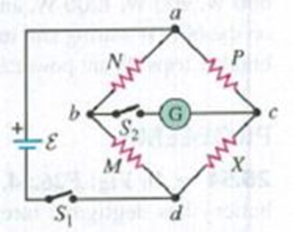
The Wheatstone Bridge. The circuit shown in Fig. P26.74, called a Wheatstone bridge, is used to determine the value of an unknown resistor X by comparison with three resistors M, N, and P whose resistances can be varied. For each setting, the resistance of each resistor is precisely known. With switches S1 and S2 closed, these resistors are varied until the current in the galvanometer G is zero; the bridge is then said to be balanced. (a) Show that under this condition the unknown resistance is given by X = MP/N. (This method permits very high precision in comparing resistors.) (b) If galvanometer G shows zero deflection when M = 850.0 Ω, N = 15.00 Ω, and P = 33.48 Ω, what is the unknown resistance X?
Two resistors, R1 = 00 kΩ and R2 = 3.00 kΩ, are connected in parallel and their combination is connected in series to a fully charged, 150-µF capacitor. When the switch is opened, the capacitor begins to discharged. What is the time constant for the discharge?
S
R1
C
R2
3. Given that the battery has a potential of 12 V, resistors R1
R2
= 1N and
3N, and Capacitance C = 10 µF, find the current through R2 after the
switch has been closed at t = 0 and t = ∞. Once the switch has been opened
up after some time (after capacitor is charged), find the time that the current
through R1 will reach half its initial value.
%3D
In the circuit, R= 30.0 kN and C = 0.100 µF. The capacitor is allowed to charge fully, and then the switch is changed from position a to
position b. What will the voltage across the resistor be 8.40 ms later?
R
where X = 64.1 V.
Chapter 26 Solutions
University Physics with Modern Physics (14th Edition)
Need a deep-dive on the concept behind this application? Look no further. Learn more about this topic, physics and related others by exploring similar questions and additional content below.
DC Series circuits explained - The basics working principle; Author: The Engineering Mindset;https://www.youtube.com/watch?v=VV6tZ3Aqfuc;License: Standard YouTube License, CC-BY


 Principles of Physics: A Calculus-Based TextPhysicsISBN:9781133104261Author:Raymond A. Serway, John W. JewettPublisher:Cengage Learning
 Physics for Scientists and Engineers: Foundations...PhysicsISBN:9781133939146Author:Katz, Debora M.Publisher:Cengage Learning
 Physics for Scientists and Engineers, Technology ...PhysicsISBN:9781305116399Author:Raymond A. Serway, John W. JewettPublisher:Cengage Learning
 Physics for Scientists and Engineers with Modern ...PhysicsISBN:9781337553292Author:Raymond A. Serway, John W. JewettPublisher:Cengage Learning
 College PhysicsPhysicsISBN:9781305952300Author:Raymond A. Serway, Chris VuillePublisher:Cengage Learning