
University Physics with Modern Physics (14th Edition)
14th Edition
ISBN: 9780321973610
Author: Hugh D. Young, Roger A. Freedman
Publisher: PEARSON
expand_more
expand_more
format_list_bulleted
Videos
Textbook Question
Chapter 26, Problem 26.31E
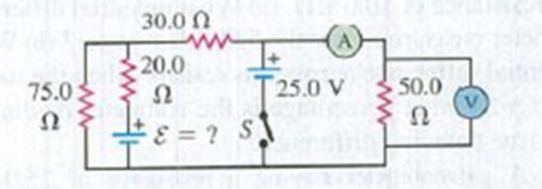
In the circuit shown in Fig. E26.31 the batteries have negligible internal resistance and the meters are both idealized. With the switch S open, the voltmeter reads 15.0 V. (a) Find the emf ε of the battery, (b) What will the ammeter read when the switch is closed?
Figure E26.31
Expert Solution & Answer

Learn your wayIncludes step-by-step video

schedule06:14
Students have asked these similar questions
26.29. In the circuit shown in Fig. E26.29 the batteries have neg-
ligible internal resistance and the meters are both idealized. With the
switch S open, the voltmeter reads 17.0 V. (a) Find the emf & of the bat-
tery. (b) What will the ammeter read when the switch is closed?
Figure E26.29
30.0 Ω
www
20.0
75.0
52
25.0 V
50.0
Ω
Ω
ε = ? $1
What is the time constant of the circuit shown in Figure OQ28.7? Each of the five resistors has resistance R. and each of the five capacitors has capacitance C. The internal resistance of the battery is negligible. (a) RC. (b) 5RC. (c) 10RC (d) 25RC (e) none of those answers
The emf source, E. of the circuit shown in the figure has negligible internal resistance. The resistors have resistances R= 6.62 and R,=4.92. The capacitor has a capacitance C 13.4 uF
When the capacitor is fully charged, the magnitude of the charge on its plates is Q
17.1 uC.
What is E in units of Volts?
R2
O 4.4
O 2.2
R1
O 3.1
O 0.22
O 1.1
Chapter 26 Solutions
University Physics with Modern Physics (14th Edition)
Ch. 26.1 - Suppose all three of the resistors shown in Fig....Ch. 26.2 - Subtract Eq. (1) from Eq. (2) in Example 26.6. To...Ch. 26.3 - You want to measure the current through and the...Ch. 26.4 - The energy stored in a capacitor is equal to...Ch. 26.5 - To prevent the circuit breaker in Example 26.14...Ch. 26 - In which 120-V light bulb does the filament have...Ch. 26 - Two 120-V light bulbs, one 25-W and one 200-W,...Ch. 26 - You connect a number of identical light bulbs to a...Ch. 26 - In the circuit shown in Fig. Q26.4, three...Ch. 26 - If two resistors R1 and R2 (R2 R1) are connected...
Ch. 26 - If two resistors R1 and R2 (R2 R1) are connected...Ch. 26 - A battery with no internal resistance is connected...Ch. 26 - A resistor consists of three identical metal...Ch. 26 - A light bulb is connected in the circuit shown in...Ch. 26 - A real battery, having nonnegligible internal...Ch. 26 - If the battery in Discussion Question Q26.10 is...Ch. 26 - Consider the circuit shown in Fig. Q26.12. What...Ch. 26 - Is it possible to connect resistors together in a...Ch. 26 - The battery in the circuit shown in Fig. Q26.14...Ch. 26 - In a two-cell flashlight, the batteries are...Ch. 26 - Identical light bulbs A, B, and C are connected as...Ch. 26 - The emf of a flashlight battery is roughly...Ch. 26 - Will the capacitors in the circuits shown in Fig....Ch. 26 - Verify that the time constant RC has units of...Ch. 26 - For very large resistances it is easy to construct...Ch. 26 - When a capacitor, battery, and resistor are...Ch. 26 - A uniform wire of resistance R is cut into three...Ch. 26 - A machine part has a resistor X protruding from an...Ch. 26 - A resistor with R1 = 25.0 is connected to a...Ch. 26 - A 42- resistor and a 20- resistor are connected in...Ch. 26 - A triangular array of resistors is shown in Fig....Ch. 26 - For the circuit shown in Fig. E26.6 both meters...Ch. 26 - For the circuit shown in Fig. E26.7 find the...Ch. 26 - Three resistors having resistances of 1.60 , 2.40...Ch. 26 - Now the three resistors of Exercise 26.8 are...Ch. 26 - Power Rating of a Resistor. The power rating of a...Ch. 26 - In Fig. E26.11, R1, = 3.00 , R2 = 6.00 , and R3=...Ch. 26 - In Fig. E26.11 the battery has emf 35.0 V and...Ch. 26 - Compute the equivalent resistance of the network...Ch. 26 - Compute the equivalent resistance of the network...Ch. 26 - In the circuit of Fig. E26.15, each resistor...Ch. 26 - Consider the circuit shown in Fig. E26.16. The...Ch. 26 - In the circuit shown in Fig. E26.17, the voltage...Ch. 26 - In the circuit shown in Fig. E26.18, = 36.0 V,...Ch. 26 - CP In the circuit in Fig. E26.19, a 20.0- resistor...Ch. 26 - In the circuit shown in Fig. E26.20, the rate at...Ch. 26 - Light Bulbs in Series and in Parallel. Two light...Ch. 26 - Light Bulbs in Series. A 60-W, 120-V light bulb...Ch. 26 - In the circuit shown in Fig. E26.23, ammeter A1...Ch. 26 - The batteries shown in the circuit in Fig. E26.24...Ch. 26 - In the circuit shown in Fig. E26.25 find (a) the...Ch. 26 - Find the emfs 1 and 2 in the circuit of Fig....Ch. 26 - In the circuit shown in Fig. E26.27, find (a) the...Ch. 26 - In the circuit shown in Fig. E26.28, find (a) the...Ch. 26 - The 10.00-V battery in Fig. E26.28 is removed from...Ch. 26 - The 5.00-V battery in Fig. E26.28 is removed from...Ch. 26 - In the circuit shown in Fig. E26.31 the batteries...Ch. 26 - In the circuit shown in Fig. E26.32 both batteries...Ch. 26 - In the circuit shown in Fig. E26.33 all meters are...Ch. 26 - In the circuit shown in Fig. E26.34, the 6.0-...Ch. 26 - The resistance of a galvanometer coil is 25.0 ,...Ch. 26 - The resistance of the coil of a pivoted coil...Ch. 26 - A circuit consists of a series combination of...Ch. 26 - A galvanometer having a resistance of 25.0 has a...Ch. 26 - A capacitor is charged to a potential of 12.0 V...Ch. 26 - You connect a battery, resistor, and capacitor as...Ch. 26 - A 4.60-F capacitor that is initially uncharged is...Ch. 26 - You connect a battery, resistor, and capacitor as...Ch. 26 - CP In the circuit shown in Fig. E26.43 both...Ch. 26 - A 12.4-F capacitor is connected through a 0.895-M...Ch. 26 - An emf source with = 120 V, a resistor with R =...Ch. 26 - A resistor and a capacitor are connected in series...Ch. 26 - CP In the circuit shown in Fig. E26.47 each...Ch. 26 - A 1.50-F capacitor is charging through a 12.0-...Ch. 26 - In the circuit in Fig. E26.49 the capacitors are...Ch. 26 - A 12.0-F capacitor is charged to a potential of...Ch. 26 - In the circuit shown in Fig. E26.51, C = 5.90 F, ...Ch. 26 - Prob. 26.52ECh. 26 - A 1500-W electric beater is plugged into the...Ch. 26 - In Fig. P26.54, the battery has negligible...Ch. 26 - The two identical light bulbs in Example 26.2...Ch. 26 - Each of the three resistors in Fig. P26.56 has a...Ch. 26 - (a) Find the potential of point a with respect to...Ch. 26 - CP For the circuit shown in Fig. P26.58 a 20.0-...Ch. 26 - Calculate the three currents I1, I2, and I3...Ch. 26 - What must the emf in Fig. P26.60 be in order for...Ch. 26 - Find the current through each of the three...Ch. 26 - (a) Find the current through the battery and each...Ch. 26 - Consider the circuit shown in Fig. P26.63. (a)...Ch. 26 - In the circuit shown in Fig. P26.64, = 24.0 V,...Ch. 26 - In the circuit shown in Fig. P26.65, the current...Ch. 26 - In the circuit shown in Fig. P26.66 all the...Ch. 26 - Figure P26.67 employs a convention often used in...Ch. 26 - Three identical resistors are connected in series....Ch. 26 - A resistor R1 consumes electrical power P1 when...Ch. 26 - The capacitor in Fig. F26.70 is initially...Ch. 26 - A 2.00-F capacitor that is initially uncharged is...Ch. 26 - A 6.00-F capacitor that is initially uncharged is...Ch. 26 - Point a in Fig. P26.73 is maintained at a constant...Ch. 26 - The Wheatstone Bridge. The circuit shown in Fig....Ch. 26 - (See Problem 26.67.) (a) What is the potential of...Ch. 26 - A 2.36-F capacitor that is initially uncharged is...Ch. 26 - A 224- resistor and a 589- resistor are connected...Ch. 26 - A resistor with R = 850 is connected to the...Ch. 26 - A capacitor that is initially uncharged is...Ch. 26 - DATA You set up the circuit shown in Fig. 26.22a,...Ch. 26 - DATA You set up the circuit shown in Fig. 26.20....Ch. 26 - DATA The electronics supply company where you work...Ch. 26 - An Infinite Network. As shown in Fig. P26.83, a...Ch. 26 - Suppose a resistor R lies along each edge of a...Ch. 26 - BIO Attenuator Chains and Axons. The infinite...Ch. 26 - Assume that a typical open ion channel spanning an...Ch. 26 - In a simple model of an axon conducting a nerve...Ch. 26 - Cell membranes across a wide variety of organisms...
Additional Science Textbook Solutions
Find more solutions based on key concepts
For a solid, we also define the linear thermal expansion coefficient, a, as the fractional increase in length p...
An Introduction to Thermal Physics
What class of motion, natural or violent, did Aristotle attribute to motion of the Moon?
Conceptual Physics (12th Edition)
55. Cetyl alcohol, C16H34O, is a common ingredient of soaps and shampoos. It was once commonly obtained from wh...
Conceptual Physical Science (6th Edition)
Briefly discuss the possibility of life on Jupiter and Saturn.
Life in the Universe (4th Edition)
A test charge of +2C is placed halfway between a charge of +6 C and another of +4 /C separated by 10 cm. (a) Wh...
College Physics
15. a. Compute the binding energy of the reactants and of the products in the nuclear fusion reaction
3H + 3He ...
College Physics: A Strategic Approach (3rd Edition)
Knowledge Booster


Learn more about
Need a deep-dive on the concept behind this application? Look no further. Learn more about this topic, physics and related others by exploring similar questions and additional content below.Similar questions
- In the figure the ideal batteries have emfs &₁ = 20.4 V, E2 = 9.31 V, and E3 = 5.30 V, and the resistances are each 1.90 02. What are the (a) size and (b) direction (left or right) of current i₁? (c) Does battery 1 supply or absorb energy, and (d) what is its power? (e) Does battery 2 supply or absorb energy, and (f) what is its power? (g) Does battery 3 supply or absorb energy, and (h) what is its power? #183 D www www www 4 4- +18₂ 4arrow_forwardWhen switch S in Fig. E25.33 is open, the voltmeter V of the battery reads 3.08 V. When the switch is closed, the voltmeter reading drops to 2.97 V, and the ammeter A reads 1.65 A. Find the emf, the internal resistance of the battery, and the circuit resistance R. Assume that the two meters are ideal, so they don’t affect the circuit.arrow_forwardA solar cell generates a potential difference of 0.17 V when a 550 resistor is connected across it, and a potential difference of 0.24 V when a 970 resistor is substituted. What are the (a) internal resistance and (b) emf of the solar cell? (c) The area of the cell is 1.2 cm² and the rate per unit area at which it receives energy from light is 4.9 mW/cm². What is the efficiency of the cell for converting light energy to thermal energy in the 970 2 external resistor? (a) Number (b) Number (c) Number i Units Units Units Ω V perarrow_forward
- sv 26.31 In the circuit shown in Fig. E26.31 all meters are idealized and the batteries have no appreciable internal resistance. (a) Find the read- ing of the voltmeter with the switch S open. Which point is at a higher poten- tial: a or b? (b) With S closed, find the reading of the voltmeter and the amme- 25.0 V 75.0 Ω ter. Which way (up or down) does the current flow through the switch? Figure E26.31 100.0 Ω a L15.0arrow_forwardA series circuit is comprised of a 200VDC battery, a switch, a 1 kΩ resistor and a 10000 µF capacitor. Initially the switch is open and the capacitor is uncharged. What is the resistor voltage 29 seconds after the switch is closed? answer should be in V.arrow_forwardOn a cold day a battery has a terminal voltage of V₁ = 12.3 V and an internal resistance of r₁ = 0.0065 92. On a warm day the battery has a terminal voltage of V₂ = 11.64 V and an internal resistance of r2 = 0.028 2. The device it powers draws the same current at both temperatures. Assume the emf of the battery does not depend on temperature. Enter an expression for the current, I, in terms of the given quantities. Calculate the current, I, in amperes. What is the battery's emf, in volts?arrow_forward
- www In the figure the ideal batteries have emfs &₁ = 18.3 V, 82 = 9.31 V, and 3 = 5.50 V, and the resistances are each 2.00 2. What are the (a) size and (b) direction (left or right) of current i₁? (c) Does battery 1 supply or absorb energy, and (d) what is its power? (e) Does battery 2 supply or absorb energy, and (f) what is its power? (g) Does battery 3 supply or absorb energy, and (h) what is its power? ww 83 www ww www wwarrow_forwardConsider the circuit shown in Figure. The emf source has negligible internal resistance. The resistors have resistances R1= 6Ω and R2= 4Ω. The capacitor has capacitance C=9 μF. When the capacitor is fully charged, the magnitude of the charge on its plates is Q=36. Calculate the emf ε.arrow_forwardChapter 27, Problem 076 GO In the figure the ideal batteries have emfs &₁ = 18.5 V, &2 = 9.23 V, and 3 = 4.60 V, and the resistances are each 1.50 2. What are the (a) size and (b) direction (left or right) of current i₁? (c) Does battery 1 supply or absorb energy, and (d) what is its power? (e) Does battery 2 supply or absorb energy, and (f) what is its power? (g) Does battery 3 supply or absorb energy, and (h) what is its power? H • દ Floo + =1&₂arrow_forward
- 24.0 V 4.00 A R 4.00 A Figure N 8. Consider the circuit shown in Figure b. The terminal voltage of the 24.0 V battery is 21.2 V. What is a) the internal resistance r of the battery; b) the resistance R of the circuit resistor???arrow_forwardWhat are the expected readings of (a) the ideal ammeter and (b) the ideal voltmeter in Figure?arrow_forward26.23. In the circuit shown in Fig. E26.23 find (a) the current in re- sistor R; (b) the resistance R; (c) the unknown emf E. (d) If the circuit is broken at point x, what is the current in resistor R? Figure E26.23 28.0 V R E 4.00 A - ww x 6.00 Ω 6.00 A 3.00 Ω 26.25 In the circuit shown in Fig. E26.25, find (a) the current in the 3.00 resistor; (b) the unknown emfs &₁ and E2; (c) the resistance R. Note that three currents are given. Figure E26.25 2,00 A R www 6.00 Ω 15.00 A 4.00 ΩΣ 3.00 A • 3.00 Ωarrow_forward
arrow_back_ios
SEE MORE QUESTIONS
arrow_forward_ios
Recommended textbooks for you
 Physics for Scientists and Engineers: Foundations...PhysicsISBN:9781133939146Author:Katz, Debora M.Publisher:Cengage Learning
Physics for Scientists and Engineers: Foundations...
Physics
ISBN:9781133939146
Author:Katz, Debora M.
Publisher:Cengage Learning
DC Series circuits explained - The basics working principle; Author: The Engineering Mindset;https://www.youtube.com/watch?v=VV6tZ3Aqfuc;License: Standard YouTube License, CC-BY