VECTOR MECHANICS FOR ENGINEERS W/CON >B
12th Edition
ISBN: 9781260804638
Author: BEER
Publisher: MCG
bartleby

Concept explainers

bartleby

Videos

Textbook Question
Book Icon
Chapter 2.5, Problem 2.107P

Three cables are connected at A, where the forces P and Q are applied as shown. Knowing that Q = 0, find the value of P for which the tension in cable AD is 305 N.
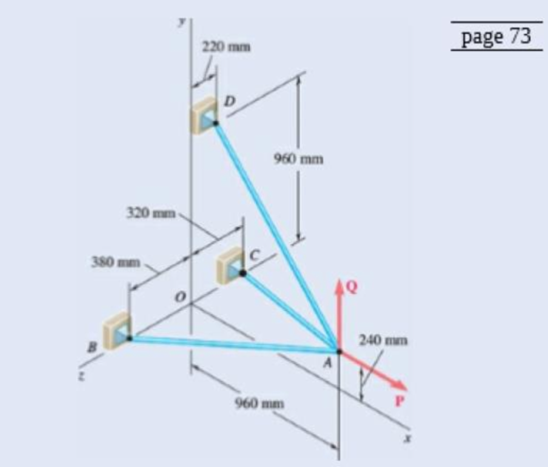
Chapter 2.5, Problem 2.107P, Three cables are connected at A, where the forces P and Q are applied as shown. Knowing that Q = 0,

Fig.P2.107and P2.108

Expert Solution & Answer
Check Mark
To determine

The value of P shown in figure P2.107 in the textbook for which tension in the cable shown AD is 305N.

Answer to Problem 2.107P

The force P at the point A shown in figure P2.107 is 960N_.

Explanation of Solution

The sketch of the cables connected at A, where the forces P and Q applied is shown in below figure1.
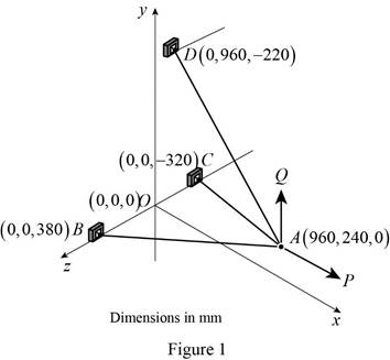
VECTOR MECHANICS FOR ENGINEERS W/CON >B, Chapter 2.5, Problem 2.107P , additional homework tip  1

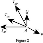
Free body diagram at A is shown in figure 2.

VECTOR MECHANICS FOR ENGINEERS W/CON >B, Chapter 2.5, Problem 2.107P , additional homework tip  2

Here, TAB is the magnitude of tension in cable AB, TAC is the magnitude of tension in cable AC, TAD is the magnitude of tension in the cable AD , P is the magnitude of the force exerted in the x direction and Q is the magnitude of force exerted in the y direction.

The force Q exerted at point A is zero and the tension in cable AD is 305N.

Let TAB, TAC, and P are the tension vector in cable AB, AC, AD and force exerted in the x direction respectively and Q is the force at A along the y direction.

Let i , j and k are the unit vectors along the of x,yandz direction.

Write the equation of vector distance AB.

AB=(x2x1)i+(y2y1)j+(z2z1)k (I)

Here, AB is the vector distance of the cable AB, the variables x1,y1and z1 are the coordinates of point A and x2,y2and z2 are the coordinates of point B.

Write the vector distance of the cable AC.

AC=(x3x1)i+(y3y1)j+(z3z1)k (II)

Here, AC is the vector distance of the cable AC, the variables x1,y1and z1 are the coordinates of point A and x3,y3and z3 are the coordinates of point C.

Write the vector distance of the cable AD.

AD=(x4x1)i+(y4y1)j+(z4z1)k (III)

Here, AD is the vector distance of the cable AD, the variables x1,y1and z1 are the coordinates of point A and x4,y4and z4 are the coordinates of point D.

Write the equation of tension in the cable AB.

TAB=λABTAB (IV)

Here, TAB is the tension in the cable AB , TAB is the magnitude of the tension in the cable AB and λAB is the unit vector in the direction of AB.

Write the equation of λAB.

λAB=ABAB (V)

Write the equation of tension in the cable AC.

TAC=λACTAC (VI)

Here, TAC is the tension in the cable AC , TAC is the magnitude of the tension in the cable AC and λAC is the unit vector in the direction of AC.

Write the equation of λAC.

λAC=ACAC (VII)

Write the equation of tension in the cable AD.

TAD=λADTAD (VIII)

Here, TAD is the tension in the cable AD , TAD is the magnitude of the tension in the cable AD and λAD is the unit vector in the direction of AD.

Write the equation of λAD.

λAD=ADAD (IX)

Write the equation of force exerting at point A along x direction.

P=Pj (X)

Here, P is the vector notation of weight of the body and P is the magnitude of weight.

Write the equation of force exerting at point A along y direction.

Q=Qj

Write the equilibrium condition for the forces at A.

F=0

Here, F is the force

The above equation implies that at equilibrium, total force acting on the cable at A is zero.

Refer figure 2 and write the equation of total force.

TAB+TAC+TAD+P+Q=0

Since Q=0N, write the above equation in simplified form

TAB+TAC+TAD+P=0 (XI)

Conclusion:

Substitute 960mm for x1 , 240mm for y1 , 0mm for z1 , 0mm for x2 , 0mm for y2 and 380mm for z2 in equation (I) to get AB.

AB=(960mm)i(240mm)j+(380mm)k

Calculate the magnitude of AB.

AB=(960mm)2+(240mm)2+(320mm)2=1060mm

Substitute 960mm for x1 , 240mm for y1 , 0mm for z1 , 0mm for x3 , 0mm for y3 and 320mm for z3 in equation (II) to get AC.

AC=(960mm)i(240mm)j(320mm)k

Calculate the magnitude of AC.

AC=(960mm)2+(240mm)2+(320mm)2=1040mm

Substitute 960mm for x1 , 240mm for y1 , 0mm for z1 ,0mm for x4 , 960mm for y4 and 0mm for z4 in equation (III) to get AD.

AD=(960mm)i+(720mm)j(220mm)k

Calculate the magnitude of AD.

AD=(960mm)2+(720mm)2+(220mm)2=1220mm

Substitute (960mm)i(240mm)j+(380mm)k for AB and 1060mm for AB in equation (V) to get λAB.

λAB=(960mm)i(240mm)j+(380mm)k1060mm=4853i1253j+1953k

Substitute 4853i1253j+1953k for λAB in equation (IV) to get TAB.

TAB=(4853i1253j+1953k)TAB

Substitute (960mm)i(240mm)j(320mm)k for AC and 7.40mm for AC in equation
(VII) to get λAC.

λAC=(960mm)i(240mm)j(320mm)k1040mm=1213i313j413k

Substitute 1213i313j413k for λAC in equation (VI) to get TAC.

TAC=(1213i313j413k)TAC

Substitute (960mm)i+(720mm)j(220mm)k for AD and 6.50mm for AD in equation (IX) to get λAD.

λAD=(960mm)i+(720mm)j(220mm)k1220mm

Substitute (960mm)i+(720mm)j(220mm)k1220mm for λAD and 305N for TAD in equation (VIII) to get TAD.

TAD=((960mm)i+(720mm)j(220mm)k1220mm)(305N)=(240N)i+(180N)j(55N)k

Substitute (4853i1253j+1953k)TAB for TAB , (1213i313j413k)TAC for TAC , (240N)i+(180N)j(55N)k and Pi for P in the in equation (XI) to get force P exerted at point A.

(4853i1253j+1953k)TAB+(1213i313j413k)TAC+(240N)i+(180N)j(55N)k+Pj=0(4853TAB1213TAC240N+P)i+(1253TAB313TAC+180N)j+(+1953TAB413TAC55N)k=0

Since total force is zero. Equate force along each direction as zero.

4853TAB1213TAC240N+P=0 (XII)

1253TAB313TAC+180N=0 (XIII)

1953TAB413TAC55N=0 (XIV)

Multiply equation (XIII) by 43 to modify the equation.

48159TAB413TAC+180N=0 (XV)

Add above equation with equation (XIV) to get TAB.

48159TAB+413TAC240N+(1953TAB413TAC55N)=048159TAB240N+(1953TAB55N)=0TAB=446.71N

Substitute 446.71N for TAB in equation (XIV) to get TAC.

1953(446.71N)413TAC55N=0TAC=341.71N

Substitute 341.71N for TAC, 446.71N for TAB in equation (XII) to get P.

4853(446.71N)1213(341.71N)240N+P=0P=960N

Therefore, the force P exerted at A is 960Ni_.

Want to see more full solutions like this?

Subscribe now to access step-by-step solutions to millions of textbook problems written by subject matter experts!
Students have asked these similar questions
How do i solve this problem?
Q4/ A compressor is driven motor by mean of a flat belt of thickness 10 mm and a width of 250 mm. The motor pulley is 300 mm diameter and run at 900 rpm and the compressor pulley is 1500 mm diameter. The shaft center distance is 1.5 m. The angle of contact of the smaller pulley is 220° and on the larger pulley is 270°. The coefficient of friction between the belt and the small pulley is 0.3, and between the belt and the large pulley is 0.25. The maximum allowable belt stress is 2 MPa and the belt density is 970 kg/m³. (a) What is the power capacity of the drive and (b) If the small pulley replaced by V-grooved pulley of diameter 300 mm, grooved angle of 34° and the coefficient of friction between belt and grooved pulley is 0.35. What will be the power capacity in this case, assuming that the diameter of the large pulley remain the same of 1500 mm.
You are tasked with designing a power drive system to transmit power between a motor and a conveyor belt in a manufacturing facility as illustrated in figure. The design must ensure efficient power transmission, reliability, and safety. Given the following specifications and constraints, design drive system for this application: Specifications: Motor Power: The electric motor provides 10 kW of power at 1,500 RPM. Output Speed: The output shaft should rotate at 150 rpm. Design Decisions: Transmission ratio: Determine the necessary drive ratio for the system. Shaft Diameter: Design the shafts for both the motor and the conveyor end. Material Selection: Choose appropriate materials for the gears, shafts. Bearings: Select suitable rolling element bearings. Constraints: Space Limitation: The available space for the gear drive system is limited to a 1-meter-long section. Attribute 4 of CEP Depth of knowledge required Fundamentals-based, first principles analytical approach…

Chapter 2 Solutions

VECTOR MECHANICS FOR ENGINEERS W/CON >B

Ch. 2.1 - A steel tank is to be positioned in an excavation....Ch. 2.1 - A steel tank is to be positioned in an excavation....Ch. 2.1 - A steel tank is to be positioned in an excavation....Ch. 2.1 - For the hook support of Prob. 2.10, determine by...Ch. 2.1 - The barge B is pulled by two tugboats A and C. At...Ch. 2.1 - Solve Prob. 2.1 by trigonometry.Ch. 2.1 - Solve Prob. 2.4 by trigonometry.Ch. 2.1 - For the stake of Prob. 2.5, knowing that the...Ch. 2.1 - Two structural members A and B are bolted to a...Ch. 2.1 - Two structural members A and B are bolted to a...Ch. 2.2 - Determine the x and y components of each of the...Ch. 2.2 - Determine the x and y components of each of die...Ch. 2.2 - Determine the x and y components of each of the...Ch. 2.2 - Determine the x and y components of each of the...Ch. 2.2 - Member BC exerts on member AC a force P directed...Ch. 2.2 - Member BD exerts on member ABC a force P directed...Ch. 2.2 - Prob. 2.27PCh. 2.2 - Cable AC exerts on beam AD a force P directed...Ch. 2.2 - The hydraulic cylinder BD exerts on member ABC a...Ch. 2.2 - The guy wire BD exerts on the telephone pole AC a...Ch. 2.2 - Determine the resultant of the three forces of...Ch. 2.2 - Determine the resultant of the three forces of...Ch. 2.2 - Determine the resultant of the three forces of...Ch. 2.2 - Determine the resultant of the three forces of...Ch. 2.2 - Knowing that = 35, determine the resultant of the...Ch. 2.2 - Knowing that the tension in cable BC is 725 N,...Ch. 2.2 - Knowing that = 40, determine the resultant of the...Ch. 2.2 - Knowing that = 75, determine the resultant of the...Ch. 2.2 - PROBLEM 2.39 A collar that can slide on a vertical...Ch. 2.2 - PROBLEM 2.40 For the beam of Problem 2.36,...Ch. 2.2 - PROBLEM 2.41 Determine (a) the required tension in...Ch. 2.2 - PROBLEM 2.42 For the block of Problems 2.37 and...Ch. 2.3 - Two cables are tied together at C and loaded as...Ch. 2.3 - Two forces of magnitude TA = 8 kips and TB = 15...Ch. 2.3 - The 60-lb collar A can slide on a frictionless...Ch. 2.3 - A chairlift has been stopped in the position...Ch. 2.3 - Two cables are tied together at C and are loaded...Ch. 2.3 - Two cables are tied together at C and are loaded...Ch. 2.3 - Two cables are tied together at C and loaded as...Ch. 2.3 - Two cables are tied together at C and are loaded...Ch. 2.3 - Prob. 2.47PCh. 2.3 - Knowing that = 20, determine the tension (a) in...Ch. 2.3 - Two cables are tied together at C and are loaded...Ch. 2.3 - Two cables are tied together at C and are loaded...Ch. 2.3 - Prob. 2.51PCh. 2.3 - Two forces P and Q are applied as shown to an...Ch. 2.3 - A welded connection is in equilibrium under the...Ch. 2.3 - A welded connection is in equilibrium under the...Ch. 2.3 - A sailor is being rescued using a boatswains chair...Ch. 2.3 - A sailor is being rescued using a boatswains chair...Ch. 2.3 - For the cables of Prob. 2.44, find the value of ...Ch. 2.3 - For the cables of Prob. 2.46, it is known that the...Ch. 2.3 - For the situation described in Fig. P2.48,...Ch. 2.3 - Two cables tied together at C are loaded as shown....Ch. 2.3 - A movable bin and its contents have a combined...Ch. 2.3 - Prob. 2.62PCh. 2.3 - Collar A is connected as shown to a 50-lb load and...Ch. 2.3 - Collar A is connected as shown to a 50-lb load and...Ch. 2.3 - A cable loop of length 1.5 m is placed around a...Ch. 2.3 - A 200-kg crate is to be supported by the...Ch. 2.3 - A 600-lb crate is supported by several...Ch. 2.3 - Solve parts b and d of Prob. 2.67, assuming that...Ch. 2.3 - A load Q is applied to the pulley C, which can...Ch. 2.3 - An 1800-N load Q is applied to pulley C, which can...Ch. 2.4 - Determine (a) the x, y, and z components of the...Ch. 2.4 - Determine (a) the x, y, and z components of the...Ch. 2.4 - A gun is aimed at a point A located 35 east of...Ch. 2.4 - Solve Prob. 2.73 assuming that point A is located...Ch. 2.4 - The angle between the guy wire AB and the mast is...Ch. 2.4 - The angle between the guy wire AC and the mast is...Ch. 2.4 - Cable AB is 65 ft long, and the tension in that...Ch. 2.4 - PROBLEM 2.78 Cable AC is 70 ft long, and the...Ch. 2.4 - Determine the magnitude and direction of the force...Ch. 2.4 - Determine the magnitude and direction of the force...Ch. 2.4 - Prob. 2.81PCh. 2.4 - Prob. 2.82PCh. 2.4 - Prob. 2.83PCh. 2.4 - A force acts at the origin of a coordinate system...Ch. 2.4 - Two cables BG and BH are attached to frame ACD as...Ch. 2.4 - Two cables BG and BH are attached to frame ACD as...Ch. 2.4 - In order to move a wrecked truck, two cables are...Ch. 2.4 - In order to move a wrecked truck, two cables are...Ch. 2.4 - A rectangular plate is supported by three cables...Ch. 2.4 - A rectangular plate is supported by three cables...Ch. 2.4 - Find the magnitude and direction of the resultant...Ch. 2.4 - Prob. 2.92PCh. 2.4 - Knowing that the tension is 425 lb in cable AB and...Ch. 2.4 - Knowing that the tension is 510 lb in cable AB and...Ch. 2.4 - Prob. 2.95PCh. 2.4 - Prob. 2.96PCh. 2.4 - The boom OA carries a load P and is supported by...Ch. 2.4 - Fig. P2.97 2.98 For the boom and loading of Prob....Ch. 2.5 - Three cables are used to tether a balloon as...Ch. 2.5 - A container of mass m = 120 kg is supported by...Ch. 2.5 - A 150-lb cylinder is supported by two cables AC...Ch. 2.5 - A transmission tower is held by three guy wires...Ch. 2.5 - A container is supported by three cables that are...Ch. 2.5 - A container is supported by three cables that are...Ch. 2.5 - Three cables are used to tether a balloon as...Ch. 2.5 - Three cables are used to tether a balloon as...Ch. 2.5 - A crate is supported by three cables as shown....Ch. 2.5 - A crate is supported by three cables as shown....Ch. 2.5 - A 12-lb circular plate of 7-in. radius is...Ch. 2.5 - Solve Prob. 2.105, knowing that = 45.Ch. 2.5 - Three cables are connected at A, where the forces...Ch. 2.5 - Fig. P2.107 and P2.108 2.108 Three cables are...Ch. 2.5 - Prob. 2.109PCh. 2.5 - A rectangular plate is supported by three cables...Ch. 2.5 - A transmission tower is held by three guy wires...Ch. 2.5 - A transmission tower is held by three guy wires...Ch. 2.5 - In trying to move across a slippery icy surface, a...Ch. 2.5 - Fig. P2.113 2.114 Solve Prob. 2.113 assuming that...Ch. 2.5 - For the rectangular plate of Probs. 2.109 and...Ch. 2.5 - PROBLEM 2.116 For the cable system of Problems...Ch. 2.5 - PROBLEM 2.117 For the cable system of Problems...Ch. 2.5 - Three cables are connected at D, where an upward...Ch. 2.5 - For the transmission tower of Probs. 2.111 and...Ch. 2.5 - Three wires are connected at point D, which is...Ch. 2.5 - A container of weight W is suspended from ring A,...Ch. 2.5 - Prob. 2.122PCh. 2.5 - A container of weight W is suspended from ring A....Ch. 2.5 - Prob. 2.124PCh. 2.5 - Fig. P2.113 2.114 Solve Prob. 2.113 assuming that...Ch. 2.5 - Prob. 2.126PCh. 2 - Two forces P and Q are applied to the lid of a...Ch. 2 - Determine the x and y components of each of the...Ch. 2 - A hoist trolley is subjected to the three forces...Ch. 2 - Knowing that = 55 and that boom AC exerts on pin...Ch. 2 - Two cables are tied together at C and loaded as...Ch. 2 - Two cables tied together at C are loaded as shown....Ch. 2 - The end of the coaxial cable AE is attached to the...Ch. 2 - Prob. 2.134RPCh. 2 - Find the magnitude and direction of the resultant...Ch. 2 - Cable BAC passes through a frictionless ring A and...Ch. 2 - Collars A and B are connected by a 25-in.-lang...Ch. 2 - Fig. P2.137 and P2.138 2.138 Collars A and B are...
Knowledge Booster
Background pattern image
Mechanical Engineering
Learn more about
Need a deep-dive on the concept behind this application? Look no further. Learn more about this topic, mechanical-engineering and related others by exploring similar questions and additional content below.
Similar questions
SEE MORE QUESTIONS
Recommended textbooks for you
Text book image
Elements Of Electromagnetics
Mechanical Engineering
ISBN:9780190698614
Author:Sadiku, Matthew N. O.
Publisher:Oxford University Press
Text book image
Mechanics of Materials (10th Edition)
Mechanical Engineering
ISBN:9780134319650
Author:Russell C. Hibbeler
Publisher:PEARSON
Text book image
Thermodynamics: An Engineering Approach
Mechanical Engineering
ISBN:9781259822674
Author:Yunus A. Cengel Dr., Michael A. Boles
Publisher:McGraw-Hill Education
Text book image
Control Systems Engineering
Mechanical Engineering
ISBN:9781118170519
Author:Norman S. Nise
Publisher:WILEY
Text book image
Mechanics of Materials (MindTap Course List)
Mechanical Engineering
ISBN:9781337093347
Author:Barry J. Goodno, James M. Gere
Publisher:Cengage Learning
Text book image
Engineering Mechanics: Statics
Mechanical Engineering
ISBN:9781118807330
Author:James L. Meriam, L. G. Kraige, J. N. Bolton
Publisher:WILEY
EVERYTHING on Axial Loading Normal Stress in 10 MINUTES - Mechanics of Materials; Author: Less Boring Lectures;https://www.youtube.com/watch?v=jQ-fNqZWrNg;License: Standard YouTube License, CC-BY