
VECTOR MECHANICS FOR ENGINEERS W/CON >B
12th Edition
ISBN: 9781260804638
Author: BEER
Publisher: MCG
expand_more
expand_more
format_list_bulleted
Concept explainers
Videos
Textbook Question
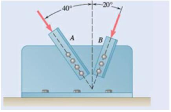
Chapter 2.1, Problem 2.19P
Two structural members A and B are bolted to a bracket as shown. Knowing that both members are in compression and that the force is 10 kN in member A and 15 kN in member B, determine by trigonometry the magnitude and direction of the resultant of the forces applied to the bracket by members A and B.
Expert Solution & Answer
Want to see the full answer?
Check out a sample textbook solution
Students have asked these similar questions
I don't want an AI solution please.
I don't want an AI solution please.
I don't want an AI solution please.
Chapter 2 Solutions
VECTOR MECHANICS FOR ENGINEERS W/CON >B
Ch. 2.1 - Two forces are applied as shown to a hook....Ch. 2.1 - Two forces are applied as shown to a bracket...Ch. 2.1 - Two forces P and Q are applied as shown at point A...Ch. 2.1 - Two forces P and Q are applied as shown at point A...Ch. 2.1 - A stake is being pulled out of the ground by means...Ch. 2.1 - A telephone cable is clamped at A to the pole AB....Ch. 2.1 - A telephone cable is clamped at A to the pole AB....Ch. 2.1 - A disabled automobile is pulled by means of two...Ch. 2.1 - A disabled automobile is pulled by means of two...Ch. 2.1 - Two forces are applied as shown to a hook support....
Ch. 2.1 - A steel tank is to be positioned in an excavation....Ch. 2.1 - A steel tank is to be positioned in an excavation....Ch. 2.1 - A steel tank is to be positioned in an excavation....Ch. 2.1 - For the hook support of Prob. 2.10, determine by...Ch. 2.1 - The barge B is pulled by two tugboats A and C. At...Ch. 2.1 - Solve Prob. 2.1 by trigonometry.Ch. 2.1 - Solve Prob. 2.4 by trigonometry.Ch. 2.1 - For the stake of Prob. 2.5, knowing that the...Ch. 2.1 - Two structural members A and B are bolted to a...Ch. 2.1 - Two structural members A and B are bolted to a...Ch. 2.2 - Determine the x and y components of each of the...Ch. 2.2 - Determine the x and y components of each of die...Ch. 2.2 - Determine the x and y components of each of the...Ch. 2.2 - Determine the x and y components of each of the...Ch. 2.2 - Member BC exerts on member AC a force P directed...Ch. 2.2 - Member BD exerts on member ABC a force P directed...Ch. 2.2 - Prob. 2.27PCh. 2.2 - Cable AC exerts on beam AD a force P directed...Ch. 2.2 - The hydraulic cylinder BD exerts on member ABC a...Ch. 2.2 - The guy wire BD exerts on the telephone pole AC a...Ch. 2.2 - Determine the resultant of the three forces of...Ch. 2.2 - Determine the resultant of the three forces of...Ch. 2.2 - Determine the resultant of the three forces of...Ch. 2.2 - Determine the resultant of the three forces of...Ch. 2.2 - Knowing that = 35, determine the resultant of the...Ch. 2.2 - Knowing that the tension in cable BC is 725 N,...Ch. 2.2 - Knowing that = 40, determine the resultant of the...Ch. 2.2 - Knowing that = 75, determine the resultant of the...Ch. 2.2 - PROBLEM 2.39 A collar that can slide on a vertical...Ch. 2.2 - PROBLEM 2.40 For the beam of Problem 2.36,...Ch. 2.2 - PROBLEM 2.41 Determine (a) the required tension in...Ch. 2.2 - PROBLEM 2.42 For the block of Problems 2.37 and...Ch. 2.3 - Two cables are tied together at C and loaded as...Ch. 2.3 - Two forces of magnitude TA = 8 kips and TB = 15...Ch. 2.3 - The 60-lb collar A can slide on a frictionless...Ch. 2.3 - A chairlift has been stopped in the position...Ch. 2.3 - Two cables are tied together at C and are loaded...Ch. 2.3 - Two cables are tied together at C and are loaded...Ch. 2.3 - Two cables are tied together at C and loaded as...Ch. 2.3 - Two cables are tied together at C and are loaded...Ch. 2.3 - Prob. 2.47PCh. 2.3 - Knowing that = 20, determine the tension (a) in...Ch. 2.3 - Two cables are tied together at C and are loaded...Ch. 2.3 - Two cables are tied together at C and are loaded...Ch. 2.3 - Prob. 2.51PCh. 2.3 - Two forces P and Q are applied as shown to an...Ch. 2.3 - A welded connection is in equilibrium under the...Ch. 2.3 - A welded connection is in equilibrium under the...Ch. 2.3 - A sailor is being rescued using a boatswains chair...Ch. 2.3 - A sailor is being rescued using a boatswains chair...Ch. 2.3 - For the cables of Prob. 2.44, find the value of ...Ch. 2.3 - For the cables of Prob. 2.46, it is known that the...Ch. 2.3 - For the situation described in Fig. P2.48,...Ch. 2.3 - Two cables tied together at C are loaded as shown....Ch. 2.3 - A movable bin and its contents have a combined...Ch. 2.3 - Prob. 2.62PCh. 2.3 - Collar A is connected as shown to a 50-lb load and...Ch. 2.3 - Collar A is connected as shown to a 50-lb load and...Ch. 2.3 - A cable loop of length 1.5 m is placed around a...Ch. 2.3 - A 200-kg crate is to be supported by the...Ch. 2.3 - A 600-lb crate is supported by several...Ch. 2.3 - Solve parts b and d of Prob. 2.67, assuming that...Ch. 2.3 - A load Q is applied to the pulley C, which can...Ch. 2.3 - An 1800-N load Q is applied to pulley C, which can...Ch. 2.4 - Determine (a) the x, y, and z components of the...Ch. 2.4 - Determine (a) the x, y, and z components of the...Ch. 2.4 - A gun is aimed at a point A located 35 east of...Ch. 2.4 - Solve Prob. 2.73 assuming that point A is located...Ch. 2.4 - The angle between the guy wire AB and the mast is...Ch. 2.4 - The angle between the guy wire AC and the mast is...Ch. 2.4 - Cable AB is 65 ft long, and the tension in that...Ch. 2.4 - PROBLEM 2.78 Cable AC is 70 ft long, and the...Ch. 2.4 - Determine the magnitude and direction of the force...Ch. 2.4 - Determine the magnitude and direction of the force...Ch. 2.4 - Prob. 2.81PCh. 2.4 - Prob. 2.82PCh. 2.4 - Prob. 2.83PCh. 2.4 - A force acts at the origin of a coordinate system...Ch. 2.4 - Two cables BG and BH are attached to frame ACD as...Ch. 2.4 - Two cables BG and BH are attached to frame ACD as...Ch. 2.4 - In order to move a wrecked truck, two cables are...Ch. 2.4 - In order to move a wrecked truck, two cables are...Ch. 2.4 - A rectangular plate is supported by three cables...Ch. 2.4 - A rectangular plate is supported by three cables...Ch. 2.4 - Find the magnitude and direction of the resultant...Ch. 2.4 - Prob. 2.92PCh. 2.4 - Knowing that the tension is 425 lb in cable AB and...Ch. 2.4 - Knowing that the tension is 510 lb in cable AB and...Ch. 2.4 - Prob. 2.95PCh. 2.4 - Prob. 2.96PCh. 2.4 - The boom OA carries a load P and is supported by...Ch. 2.4 - Fig. P2.97 2.98 For the boom and loading of Prob....Ch. 2.5 - Three cables are used to tether a balloon as...Ch. 2.5 - A container of mass m = 120 kg is supported by...Ch. 2.5 - A 150-lb cylinder is supported by two cables AC...Ch. 2.5 - A transmission tower is held by three guy wires...Ch. 2.5 - A container is supported by three cables that are...Ch. 2.5 - A container is supported by three cables that are...Ch. 2.5 - Three cables are used to tether a balloon as...Ch. 2.5 - Three cables are used to tether a balloon as...Ch. 2.5 - A crate is supported by three cables as shown....Ch. 2.5 - A crate is supported by three cables as shown....Ch. 2.5 - A 12-lb circular plate of 7-in. radius is...Ch. 2.5 - Solve Prob. 2.105, knowing that = 45.Ch. 2.5 - Three cables are connected at A, where the forces...Ch. 2.5 - Fig. P2.107 and P2.108 2.108 Three cables are...Ch. 2.5 - Prob. 2.109PCh. 2.5 - A rectangular plate is supported by three cables...Ch. 2.5 - A transmission tower is held by three guy wires...Ch. 2.5 - A transmission tower is held by three guy wires...Ch. 2.5 - In trying to move across a slippery icy surface, a...Ch. 2.5 - Fig. P2.113 2.114 Solve Prob. 2.113 assuming that...Ch. 2.5 - For the rectangular plate of Probs. 2.109 and...Ch. 2.5 - PROBLEM 2.116 For the cable system of Problems...Ch. 2.5 - PROBLEM 2.117 For the cable system of Problems...Ch. 2.5 - Three cables are connected at D, where an upward...Ch. 2.5 - For the transmission tower of Probs. 2.111 and...Ch. 2.5 - Three wires are connected at point D, which is...Ch. 2.5 - A container of weight W is suspended from ring A,...Ch. 2.5 - Prob. 2.122PCh. 2.5 - A container of weight W is suspended from ring A....Ch. 2.5 - Prob. 2.124PCh. 2.5 - Fig. P2.113 2.114 Solve Prob. 2.113 assuming that...Ch. 2.5 - Prob. 2.126PCh. 2 - Two forces P and Q are applied to the lid of a...Ch. 2 - Determine the x and y components of each of the...Ch. 2 - A hoist trolley is subjected to the three forces...Ch. 2 - Knowing that = 55 and that boom AC exerts on pin...Ch. 2 - Two cables are tied together at C and loaded as...Ch. 2 - Two cables tied together at C are loaded as shown....Ch. 2 - The end of the coaxial cable AE is attached to the...Ch. 2 - Prob. 2.134RPCh. 2 - Find the magnitude and direction of the resultant...Ch. 2 - Cable BAC passes through a frictionless ring A and...Ch. 2 - Collars A and B are connected by a 25-in.-lang...Ch. 2 - Fig. P2.137 and P2.138 2.138 Collars A and B are...
Additional Engineering Textbook Solutions
Find more solutions based on key concepts
The solid steel shaft AC has a diameter of 25 mm and is supported by smooth bearings at D and E. It is coupled ...
Mechanics of Materials (10th Edition)
Why is the study of database technology important?
Database Concepts (8th Edition)
Assume a telephone signal travels through a cable at two-thirds the speed of light. How long does it take the s...
Electric Circuits. (11th Edition)
This optional Google account security feature sends you a message with a code that you must enter, in addition ...
SURVEY OF OPERATING SYSTEMS
How is the hydrodynamic entry length defined for flow in a pipe? Is the entry length longer in laminar or turbu...
Fluid Mechanics: Fundamentals and Applications
The ____________ is always transparent.
Web Development and Design Foundations with HTML5 (8th Edition)
Knowledge Booster


Learn more about
Need a deep-dive on the concept behind this application? Look no further. Learn more about this topic, mechanical-engineering and related others by exploring similar questions and additional content below.Similar questions
- 1.7 Find the stress distribution in the beam shown in Fig. 1.23 using two beam elements. A. E. I constant M₂ T + FIGURE 1.23 A fixed-pinned beam subjected to a momentarrow_forward42 PART 1 Introduction A. E. I constant FIGURE 1.22 A fixed-pinned beam. 1.6 Find the stress distribution in the beam shown in Fig. 1.22 using two beam elements.arrow_forward1.4 Using a one-beam element idealization, find the stress distribution under a load of P for the uniform cantilever beam shown in Fig. 1.20. A, E, I constant L FIGURE 1.20 A uniform cantilever beamarrow_forward
- Mechanical engineering,FBD required.arrow_forwardSolve this problem and show all of the workarrow_forwardPlease Please use MATLAB with codes and graph. Recreate the following four Figures of the textbook using MATLAB and the appropriate parameters. Comment on your observations for each Figure. List all of the parameters that you have used. The figure is attached below.arrow_forward
- Please only step 6 (last time I asked it was cut off at that point)arrow_forwardPlease Please use a MATLAB with codes and grap. Recreate the following four Figures of the textbook using MATLAB and the appropriate parameters. Comment on your observations for each Figure. List all of the parameters that you have used. The figure attached below.arrow_forwardI REPEAT!!!!! I NEED HANDDRAWING!!!!! NOT A USELESS EXPLANATION!!!! I REPEAT SUBMIT A HANDDRAWING IF YOU CANNOT UNDERSTAND THIS SKIP IT ! I need the real handdrawing complete it by adding these : Pneumatic Valves Each linear actuator must be controlled by a directional control valve (DCV) (e.g., 5/2 or 4/2 valve). The bi-directional motor requires a reversible valve to change rotation direction. Pressure Regulators & Air Supply Include two pressure regulators as per the assignment requirement. Show the main compressed air supply line connecting all components. Limit Switches & Safety Features Attach limit switches to each actuator to detect positions. Implement a two-handed push-button safety system to control actuator movement. Connections Between Components Draw air supply lines linking the compressor, valves, and actuators. Clearly label all inputs and outputs for better understanding.arrow_forward
- I need the real handdrawing complete it by adding these : Pneumatic Valves Each linear actuator must be controlled by a directional control valve (DCV) (e.g., 5/2 or 4/2 valve). The bi-directional motor requires a reversible valve to change rotation direction. Pressure Regulators & Air Supply Include two pressure regulators as per the assignment requirement. Show the main compressed air supply line connecting all components. Limit Switches & Safety Features Attach limit switches to each actuator to detect positions. Implement a two-handed push-button safety system to control actuator movement. Connections Between Components Draw air supply lines linking the compressor, valves, and actuators. Clearly label all inputs and outputs for better understanding.arrow_forwardAn elastic bar of the length L and cross section area A is rigidly attached to the ceiling of a room, and it supports a mass M. Due to the acceleration of gravity g the rod deforms vertically. The deformation of the rod is measured by the vertical displacement u(x) governed by the following equations: dx (σ(x)) + b(x) = 0 PDE σ(x) = Edx du Hooke's law (1) b(x) = gp= body force per unit volume where E is the constant Young's modulus, p is the density, and σ(x) the axial stress in the rod. g * I u(x) L 2arrow_forwardAn elastic bar of the length L and cross section area A is rigidly attached to the ceiling of a room, and it supports a mass M. Due to the acceleration of gravity g the rod deforms vertically. The deformation of the rod is measured by the vertical displacement u(x) governed by the following equations: dx (σ(x)) + b(x) = 0 PDE σ(x) = Edx du Hooke's law (1) b(x) = gp= body force per unit volume where E is the constant Young's modulus, p is the density, and σ(x) the axial stress in the rod. g * I u(x) L 2arrow_forward
arrow_back_ios
SEE MORE QUESTIONS
arrow_forward_ios
Recommended textbooks for you
 International Edition---engineering Mechanics: St...Mechanical EngineeringISBN:9781305501607Author:Andrew Pytel And Jaan KiusalaasPublisher:CENGAGE L
International Edition---engineering Mechanics: St...
Mechanical Engineering
ISBN:9781305501607
Author:Andrew Pytel And Jaan Kiusalaas
Publisher:CENGAGE L
Engineering Basics - Statics & Forces in Equilibrium; Author: Solid Solutions - Professional Design Solutions;https://www.youtube.com/watch?v=dQBvQ2hJZFg;License: Standard YouTube License, CC-BY