
Delmar's Standard Textbook of Electricity (MindTap Course List)
6th Edition
ISBN: 9781285852706
Author: Stephen L. Herman
Publisher: Cengage Learning
expand_more
expand_more
format_list_bulleted
Concept explainers
Videos
Textbook Question
thumb_up100%
Chapter 24, Problem 1RQ
What is the phase angle relationship of current and the voltage dropped across a pure resistance?
Expert Solution & Answer
To determine
The phase angle relationship of current and voltage dropped across a pure resistance.
Answer to Problem 1RQ
The phase angle between current and voltage in a pure resistance is zero degrees.
Explanation of Solution
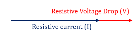
In a pure resistance the current flowing in the resistance is in phase with the voltage drop across it. We say that phase difference between both parameters is zero degrees. The same can be seen in the phasor diagram shown above.
The ohms law for pure resistive circuit is written as,
It can be seen that there is no presence of any imaginary term in the equation above. Hence the phase angle is zero degrees.
Want to see more full solutions like this?
Subscribe now to access step-by-step solutions to millions of textbook problems written by subject matter experts!
Students have asked these similar questions
Pls show neat and whole solution
If you are not an expert don't attempt it and don't use Artificial intelligence
Pls show neat and whole solution
Chapter 24 Solutions
Delmar's Standard Textbook of Electricity (MindTap Course List)
Ch. 24 - What is the phase angle relationship of current...Ch. 24 - What is the phase angle relationship of current...Ch. 24 - What is the phase angle relationship of current...Ch. 24 - An AC circuit has a frequency of 400 Hz. A 16-...Ch. 24 - If 440 V are connected to the circuit, how much...Ch. 24 - Prob. 6RQCh. 24 - What is the true power of the circuit in Question...Ch. 24 - What is the apparent power of the circuit in...Ch. 24 - What is the power factor of the circuit in...Ch. 24 - How many degrees are the voltage and current out...
Ch. 24 - You are an electrician working in a plant. A...Ch. 24 - Prob. 1PPCh. 24 - The circuit is connected to a 400-Hz line with an...Ch. 24 - The circuit is connected to a 60-Hz line. The...Ch. 24 - This circuit is connected to a 1000-Hz line. The...Ch. 24 - A series RLC circuit contains a 4-k resistor, an...Ch. 24 - A series RLC circuit contains a resistor with a...Ch. 24 - Is the power factor in Question 6 a leading or...Ch. 24 - A series RLC circuit contains a resistor with a...Ch. 24 - A series RLC circuit has an applied voltage of 240...Ch. 24 - A series RLC circuit is connected to a 60-Hz power...
Knowledge Booster


Learn more about
Need a deep-dive on the concept behind this application? Look no further. Learn more about this topic, electrical-engineering and related others by exploring similar questions and additional content below.Similar questions
- Pls show neat and whole solutionarrow_forwardDon't use ai to answer I will report you answerarrow_forwardA three-phase transmission line supplies power to three loads at a voltage 408 Vrms (line to line). The loads are as follows: Load 1: S₁ = 100+ j50 VA Load 2: S₂ = 40-j20 VA Load 3: S3 = 10 + j0 VA Find the magnitude of the line current | Line and the combined power factor of the loads. Hint: Steral \= √3 | Vime |× | Ime | line linearrow_forward
- Can you show why the answer to this question R = 199 ohm?arrow_forward2.5. Find the half-power beamwidth (HPBW) and first-null beamwidth (FNBW), in radians and degrees, for the following normalized radiation intensities: (a) U(9) cos θ cos(20) (b) U(θ)-cos2 θ cos2(26) (c) U(θ) = cos(θ) cos(30) (0 < θ < 900,0 < φ 360) (d) U(t) = cos2(9) cos2(39) (e) U(9) = cos(29) cos(39) (f) U (ecos (20) cos (30)arrow_forwardDon't use ai to answer I will report you answerarrow_forward
- Don't use ai to answer I will report you answerarrow_forwardA 60 Hz, 230 kV, 275 km long, uncompensated three-phase transmission line consists of three conductors bundled by phase, such that each conductor in the line is of the ACSR Falcon type. The separation between each bundled conductor is d = 45 cm and the separation between each phase of the line is 2.4 m. Calculate: "The parameters R, L, C of the line in Q2/km; µH/m and nF/m. And the total values of ZL and YC in Q and S, respectively, and in polar coordinates." Generalized constants A, B, C and D of the line, according to the type of transmission line. Present the results in rectangular coordinates. If a three-phase wye load draws 3/4 of the nominal current of the 300 MW system with FP = 0.85 lagging and at 230 kV, calculate: (a) Current at the load in KA (b) Voltage at the source in KV, (c) Current at the source in kA and (d) power at the source in MVA. Obtain the results per phase. Transmission line voltage regulation percentagearrow_forwardDetermine the required EMT size for the following combination of conductors:18. Four 8 AWG Type THW and four 12 AWG Type THW:19. Three 350 kcmil and one 250 kcmil Type XHHW conductors and a 4 AWG bare conductor:20. In a nonmetallic-sheathed (Type NM) cable installation, a 10⁄3 with equipmentgrounding conductor is installed in a metal octagonal box to supply two 12⁄2 withequipment grounding conductor branch-circuit cables. What is the minimum sizebox? The box contains internal cable clampsarrow_forward
- For problems 8 and 9, determine the correct box size for each of the following conditions:8. Two nonmetallic sheathed cables with two 12 AWG conductors, an equipment groundingconductor, and a switch in a metal box without a plaster ring.9. A raceway run serving a series of luminaires, connected to a total of three circuits. Theluminaires are supplied by 120 volts from a 3-phase, 4-wire system. Each box will containtwo circuits running through the box and a third circuit connected to a luminaire, which issupported by a luminaire stud in the box. Use 12 AWG Type THHN conductors.arrow_forward28. The minimum size raceway for the following conductors is: a. Three, 250 kcmil conductors with XHHW insulation b. One, 3⁄0 AWG conductor with XHHW insulation c. One, 4 AWG conductor with XHHW insulation29. The minimum size raceway for the following conductors is: a. Twelve, 6 AWG conductors with THHN insulation b. Nine, 8 AWG conductors with THHN insulation c. Eighteen, 10 AWG conductor with THHN insulation d. One, 10 AWG equipment grounding conductor with THHN insulation30. The minimum size wireway for the following with parallel conductors is: a. Two sets of three, 250 kcmil conductors with XHHW insulation b. Two, 3⁄0 AWG conductors with XHHW insulation c. 1, 4 AWG conductor with XHHW insulation d. The conductors terminate on three power distribution blocks. Each one has adimension of 4 in. wide and 3 in. high:arrow_forwardbox fill calculationsarrow_forward
arrow_back_ios
SEE MORE QUESTIONS
arrow_forward_ios
Recommended textbooks for you
 Delmar's Standard Textbook Of ElectricityElectrical EngineeringISBN:9781337900348Author:Stephen L. HermanPublisher:Cengage Learning
 Electricity for Refrigeration, Heating, and Air C...Mechanical EngineeringISBN:9781337399128Author:Russell E. SmithPublisher:Cengage Learning
 Power System Analysis and Design (MindTap Course ...Electrical EngineeringISBN:9781305632134Author:J. Duncan Glover, Thomas Overbye, Mulukutla S. SarmaPublisher:Cengage Learning
Delmar's Standard Textbook Of Electricity
Electrical Engineering
ISBN:9781337900348
Author:Stephen L. Herman
Publisher:Cengage Learning
Electricity for Refrigeration, Heating, and Air C...
Mechanical Engineering
ISBN:9781337399128
Author:Russell E. Smith
Publisher:Cengage Learning
Power System Analysis and Design (MindTap Course ...
Electrical Engineering
ISBN:9781305632134
Author:J. Duncan Glover, Thomas Overbye, Mulukutla S. Sarma
Publisher:Cengage Learning
What is a Thyristor? - A Galco TV Tech Tip; Author: GalcoTV;https://www.youtube.com/watch?v=LBb_Qz7J3zA;License: Standard Youtube License