Electric Motor Control
10th Edition
ISBN: 9781133702818
Author: Herman
Publisher: CENGAGE L
expand_more
expand_more
format_list_bulleted
Concept explainers
Textbook Question
Chapter 21, Problem 8SQ
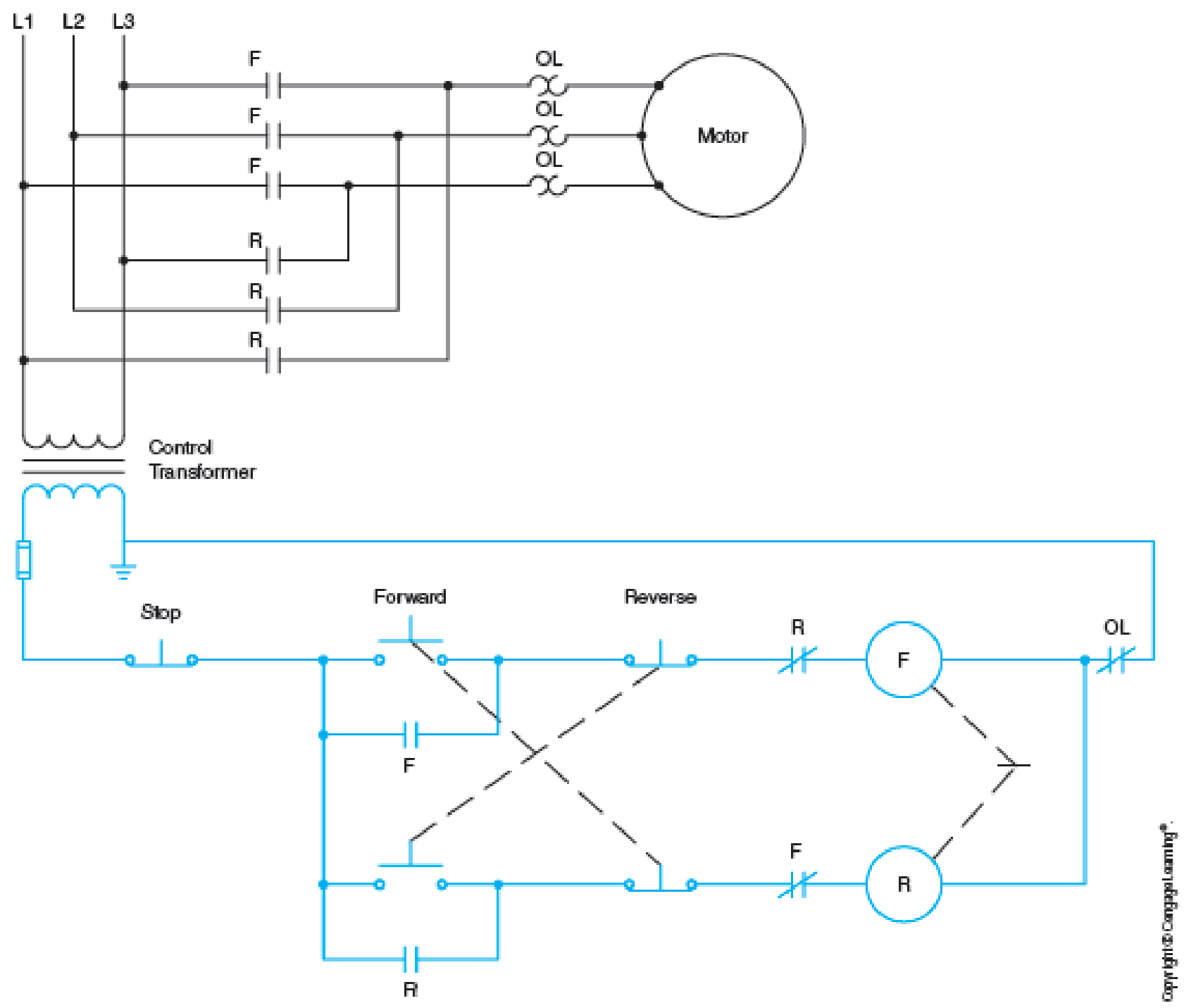
What is the sequence of the operations if the limit switches, shown in Figure 21–6, are used. (Limit switches were covered in Unit 13.)

Fig. 21–6 Elementary diagram of the reversing starter shown in Figure 21–1. The
Expert Solution & Answer
Trending nowThis is a popular solution!

Students have asked these similar questions
2 Find Inverse Fourier transform of
F(jw)
=
2w
-16+w2, and plot the f(t).
Need Handwritten Solution. Do not use chatgpt or AI
Solve by pen & paper without using chatgpt or AI
Mesh analysis
Chapter 21 Solutions
Electric Motor Control
Ch. 21 - How is a change in the direction of rotation of a...Ch. 21 - Prob. 2SQCh. 21 - If a reversing control circuit contains...Ch. 21 - How is auxiliary contact interlocking achieved on...Ch. 21 - After the forward coil has been energized, is the...Ch. 21 - If a mechanical interlock is the only means of...Ch. 21 - If pilot lights are to indicate which coil is...Ch. 21 - What is the sequence of the operations if the...Ch. 21 - In place of the push buttons in Figure 214, draw a...Ch. 21 - From the elementary drawing in Figure 2110,...
Knowledge Booster
Learn more about
Need a deep-dive on the concept behind this application? Look no further. Learn more about this topic, electrical-engineering and related others by exploring similar questions and additional content below.Similar questions
- 49. For the circuit below, what is the best connection of the capacitor to filte voltage? ბი DO A O BO wwwww wwwww M m H E LOADarrow_forward5.25. Determine the corner frequency resulting from Cin in Fig. 5.47(d). For simplicity, assume C₁ is a short circuit. TVDD C₁ M2 RF Vin H w - Vout Cin M₁arrow_forwardIn the below circuit, find out the value of equivalent Thevenin's voltage and Thevenin's resistance at the terminal. 2000 0.25 A 400 2 800 2 0.1 Aarrow_forward
- Q1: For the circuit shown in Figure-1, (a) Calculate the equivalent resistance of the circuit, RAB at the terminals A and B. [10] (b) When 50V dc source is switched at terminals A-B, solve for the voltage V₁ at the location shown. [10] 50V www 12Ω 10Ω 5Ω www www A + B 200 Figure-1 www 10Ω ww 25Ω 100arrow_forwarda. Write a PLC ladder diagram that allows the teacher to teach AND, OR, and XOR logic gates through using three PLC's digital input points and only one digital output point.arrow_forwardrately by PRACTICE 4.2 For the circuit of Fig. 4.5, compute the voltage across each curren source. 202 ww 3A 30 ww 4Ω S 50 www Reference node FIGURE 4.5 Ans: V3A =5.235 V; 7A = 11.47 V. 7 Aarrow_forward
- Q2) a) design and show me your steps to convert the following signal from continuous form to digital form: s(t)=3sin(3πt) -1 373 Colesarrow_forwardA sequence is defined by the relationship r[n] = [h[m]h[n+m]=hn*h-n where h[n] is a minimum-phase sequence and r[n]= 4 4 (u[n]+ 12" [n-1] 3 (a) Find R(z) and sketch the pole-zero diagram. (b) Determine the minimum-phase sequence h[n] to within a scale factor of ±1. Also, determine the z-transform H(z) of h[n].arrow_forwardusıng j-k and D flipflop design a counter that counts 0,2,1 again as shown below ın the tablearrow_forward
arrow_back_ios
SEE MORE QUESTIONS
arrow_forward_ios
Recommended textbooks for you
 Electricity for Refrigeration, Heating, and Air C...Mechanical EngineeringISBN:9781337399128Author:Russell E. SmithPublisher:Cengage Learning
 Delmar's Standard Textbook Of ElectricityElectrical EngineeringISBN:9781337900348Author:Stephen L. HermanPublisher:Cengage Learning

Electricity for Refrigeration, Heating, and Air C...
Mechanical Engineering
ISBN:9781337399128
Author:Russell E. Smith
Publisher:Cengage Learning


Delmar's Standard Textbook Of Electricity
Electrical Engineering
ISBN:9781337900348
Author:Stephen L. Herman
Publisher:Cengage Learning
Single Phase Induction Motor, How it works ?; Author: Lesics;https://www.youtube.com/watch?v=awrUxv7B-a8;License: Standard Youtube License