
Laboratory Manual for Introductory Circuit Analysis
13th Edition
ISBN: 9780133923780
Author: Robert L. Boylestad, Gabriel Kousourou
Publisher: PEARSON
expand_more
expand_more
format_list_bulleted
Concept explainers
Videos
Textbook Question
Chapter 21, Problem 4P
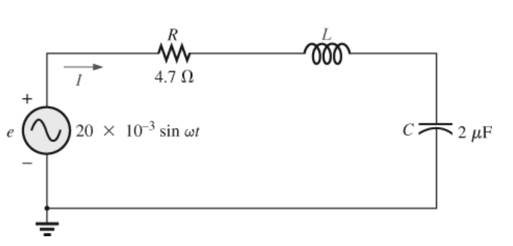
For the circuit in Fig. 21.53:
a. Find the value of L in millihenries if the resonant frequency is 1800 Hz.
b. Calculate XL and Xc How do they compare?
c. Find the magnitude of the current Irms, at resonance.
d. Find the power dissipated by the circuit at resonance.
e. What is the apparent power delivered to the system at resonance?
f. What is the power factor of the circuit at resonance?
g. Calculate the Q of the circuit and the resulting bandwidth.
h. Find the cutoff frequencies. and calculate the power dissipated by the circuit at these frequencies.
Expert Solution & Answer
Want to see the full answer?
Check out a sample textbook solution
Students have asked these similar questions
HANDWRITTEN SOLUTION NOT USING CHATGPT PLEASE
PEN & PAPER SOLUTION PLEASE NOT USING AI
Pls show neat and whole solution
Chapter 21 Solutions
Laboratory Manual for Introductory Circuit Analysis
Ch. 21 - Find the resonant s and fs for the series circuit...Ch. 21 - For the senes circuit in Fig. 21.51 : a. Find the...Ch. 21 - For the senes circuit in Fig. 21.52 : a. Find the...Ch. 21 - For the circuit in Fig. 21.53: a. Find the value...Ch. 21 - a. Find the bandwidth of a series resonant circuit...Ch. 21 - A series circuit has a resonant frequency of 10...Ch. 21 - a. The bandwidth of a series resonant circuit is...Ch. 21 - The cutoff frequencies of a series resonant...Ch. 21 - a. Design a series resonant circuit with an input...Ch. 21 - Design a series resonant circuit to have a...
Ch. 21 - A series resonant circuit is to resonate at s=2106...Ch. 21 - Prob. 12PCh. 21 - For the ideal parallel resonant circuit in Fig. 21...Ch. 21 - For the parallel resonant network in Fig. 21.55:...Ch. 21 - The network of Fig. 21.56 has a supply with an...Ch. 21 - For the network in Fig. 21.57: a. Find the value...Ch. 21 - The network shown in Fig. 21.58 is to resonate at...Ch. 21 - For the network in Fig. 21.59: a. Find the...Ch. 21 - Prob. 19PCh. 21 - It is desired that the impedance ZT of the high Q...Ch. 21 - For the network in Fig. 21.62: a. Find fp. b....Ch. 21 - For the network in Fig. 21.63: a. Find the value...Ch. 21 - Prob. 23PCh. 21 - For the network in Fig. 21.65: a. Find fs. fp, and...Ch. 21 - For the network in Fig. 21.66, the following are...Ch. 21 - Prob. 26PCh. 21 - For the parallel resonant circuit in Fig. 21.68:...Ch. 21 - Verify the results in Example 21.8, That is, show...Ch. 21 - Find fp and fm for the parallel resonant network...
Knowledge Booster


Learn more about
Need a deep-dive on the concept behind this application? Look no further. Learn more about this topic, electrical-engineering and related others by exploring similar questions and additional content below.Similar questions
- I need help with this problem and an explanation of the solution for the image described below. (Introduction to Signals and Systems)arrow_forwardI need help with this problem and an explanation of the solution for the image described below. (Introduction to Signals and Systems)arrow_forwardThe input signal in the op-amp circuit of Fig. P7.80 is given by uin(t) =V0 coswt. Assuming the op amp is operating within its linear range, obtain an expression for your(t) by applying the phasor-domain technique and then evaluate it for wRC = 1.arrow_forward
- For ui(t)=V0 coswt, obtain an expression for uout(t) in thecircuit of Fig. P7.82 and then evaluate it for V0 = 4 V, w = 400rad/s, R = 5 kW, and C = 2.5 μF.arrow_forwardCan you help me to solve the question?arrow_forwardThe input signal in the op-amp circuit of Fig. P7.81 is givenbyuin(t) = 0.5cos2000t V.Obtain an expression for uout(t) and then evaluate it forR1 = 2 kW, R2 = 10 kW, and C = 0.1 μF.arrow_forward
arrow_back_ios
SEE MORE QUESTIONS
arrow_forward_ios
Recommended textbooks for you
 Introductory Circuit Analysis (13th Edition)Electrical EngineeringISBN:9780133923605Author:Robert L. BoylestadPublisher:PEARSON
 Delmar's Standard Textbook Of ElectricityElectrical EngineeringISBN:9781337900348Author:Stephen L. HermanPublisher:Cengage Learning
 Programmable Logic ControllersElectrical EngineeringISBN:9780073373843Author:Frank D. PetruzellaPublisher:McGraw-Hill Education
 Fundamentals of Electric CircuitsElectrical EngineeringISBN:9780078028229Author:Charles K Alexander, Matthew SadikuPublisher:McGraw-Hill Education
 Electric Circuits. (11th Edition)Electrical EngineeringISBN:9780134746968Author:James W. Nilsson, Susan RiedelPublisher:PEARSON
 Engineering ElectromagneticsElectrical EngineeringISBN:9780078028151Author:Hayt, William H. (william Hart), Jr, BUCK, John A.Publisher:Mcgraw-hill Education,
Introductory Circuit Analysis (13th Edition)
Electrical Engineering
ISBN:9780133923605
Author:Robert L. Boylestad
Publisher:PEARSON
Delmar's Standard Textbook Of Electricity
Electrical Engineering
ISBN:9781337900348
Author:Stephen L. Herman
Publisher:Cengage Learning
Programmable Logic Controllers
Electrical Engineering
ISBN:9780073373843
Author:Frank D. Petruzella
Publisher:McGraw-Hill Education
Fundamentals of Electric Circuits
Electrical Engineering
ISBN:9780078028229
Author:Charles K Alexander, Matthew Sadiku
Publisher:McGraw-Hill Education
Electric Circuits. (11th Edition)
Electrical Engineering
ISBN:9780134746968
Author:James W. Nilsson, Susan Riedel
Publisher:PEARSON
Engineering Electromagnetics
Electrical Engineering
ISBN:9780078028151
Author:Hayt, William H. (william Hart), Jr, BUCK, John A.
Publisher:Mcgraw-hill Education,
What is Filter & Classification of Filters | Four Types of Filters | Electronic Devices & Circuits; Author: SimplyInfo;https://www.youtube.com/watch?v=9x1Sjz-VPSg;License: Standard Youtube License