
Fundamentals of Applied Electromagnetics (7th Edition)
7th Edition
ISBN: 9780133356816
Author: Fawwaz T. Ulaby, Umberto Ravaioli
Publisher: PEARSON
expand_more
expand_more
format_list_bulleted
Concept explainers
Videos
Textbook Question
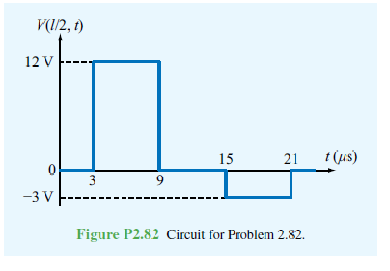
Chapter 2, Problem 82P
In response to a step voltage, the voltage waveform shown in Fig. P2.82 was observed at the midpoint of a lossless transmission line with Z0 = 50 Ω and up = 2 × 10⁸ m/s. Determine: (a) the length of the line, (b) ZL, (C) Rg, and (d) Vg.
Expert Solution & Answer
Want to see the full answer?
Check out a sample textbook solution
Students have asked these similar questions
Handwritten solution required do not use AI
Handwritten solution required not using chatgpt
Solve by Hand not using AI or chatgpt
Chapter 2 Solutions
Fundamentals of Applied Electromagnetics (7th Edition)
Ch. 2.2 - What is a transmission line? When should...Ch. 2.2 - Prob. 2CQCh. 2.2 - What constitutes a TEM transmission line?Ch. 2.2 - Prob. 4CQCh. 2.2 - Prob. 1ECh. 2.2 - Calculate the transmission line parameters at 1...Ch. 2.4 - Verify that Eq. (2.26a) indeed provides a solution...Ch. 2.4 - A two-wire air line has the following line...Ch. 2.6 - The attenuation constant represents ohmic losses....Ch. 2.6 - How is the wavelength of the wave traveling on...
Ch. 2.6 - Prob. 7CQCh. 2.6 - What is a standing-wave pattern? Why is its period...Ch. 2.6 - Prob. 9CQCh. 2.6 - For a lossless transmission line, = 20.7 cm at 1...Ch. 2.6 - A lossless transmission line uses a dielectric...Ch. 2.6 - Prob. 7ECh. 2.6 - Prob. 8ECh. 2.6 - Prob. 10ECh. 2.6 - A 140 lossless line is terminated in a load...Ch. 2.8 - What is the difference between the characteristic...Ch. 2.8 - What is a quarter-wave transformer? How can it be...Ch. 2.8 - Prob. 12CQCh. 2.8 - Prob. 13CQCh. 2.8 - if the input impedance of a lossless line is...Ch. 2.8 - Prob. 12ECh. 2.8 - A 300 feedline is to be connected to a 3 m long,...Ch. 2.9 - According to Eq. (2.102b), the instantaneous value...Ch. 2.9 - Prob. 16CQCh. 2.9 - What fraction of the incident power is delivered...Ch. 2.9 - Prob. 18CQCh. 2.9 - For a 50 lossless transmission line terminated in...Ch. 2.9 - For the line of Exercise 2-14, what is the...Ch. 2.10 - The outer perimeter of the Smith chart represents...Ch. 2.10 - What is an SWR circle? What quantities are...Ch. 2.10 - What line length corresponds to one complete...Ch. 2.10 - Which points on the SWR circle correspond to...Ch. 2.10 - Prob. 23CQCh. 2.10 - Use the Smith chart to find the values of ...Ch. 2.11 - Prob. 24CQCh. 2.11 - Prob. 25CQCh. 2.12 - What is transient analysis used for?Ch. 2.12 - Prob. 28CQCh. 2.12 - What is the difference between the bounce diagram...Ch. 2 - A transmission line of length l connects a load to...Ch. 2 - Show that the transmission-line model shown in...Ch. 2 - A 1 GHz parallel-plate transmission line consists...Ch. 2 - For the parallel-plate transmission line of...Ch. 2 - In addition to not dissipating power, a lossless...Ch. 2 - For a distortionless line [see Problem 2.13] with...Ch. 2 - Prob. 15PCh. 2 - A transmission line operating at 125 MHz has Z0 =...Ch. 2 - Prob. 17PCh. 2 - Polyethylene with r=2.25 is used as the insulating...Ch. 2 - Prob. 20PCh. 2 - Prob. 21PCh. 2 - Prob. 22PCh. 2 - Prob. 23PCh. 2 - A 50 lossless line terminated in a purely...Ch. 2 - Prob. 26PCh. 2 - Prob. 27PCh. 2 - Prob. 29PCh. 2 - Prob. 30PCh. 2 - Two half-wave dipole antennas, each with an...Ch. 2 - Prob. 34PCh. 2 - For the lossless transmission line circuit shown...Ch. 2 - A lossless transmission line is terminated in a...Ch. 2 - The input impedance of a 31 cm long lossless...Ch. 2 - FM broadcast station uses a 300 transmission line...Ch. 2 - A generator with Vg=300 V and Zg = 50 is...Ch. 2 - If the two-antenna configuration shown in Fig....Ch. 2 - For the circuit shown in Fig. P2.44, calculate the...Ch. 2 - The circuit shown in Fig. P2.45 consists of a 100 ...Ch. 2 - An antenna with a load impedance ZL=(75+j25) is...Ch. 2 - Prob. 47PCh. 2 - Use the Smith chart to determine the input...Ch. 2 - Prob. 52PCh. 2 - A lossless 50 transmission line is terminated in...Ch. 2 - A lossless 50 transmission line is terminated in...Ch. 2 - Use the Smith chart to find yL if zL = 1.5 j0.7.Ch. 2 - Prob. 59PCh. 2 - Prob. 62PCh. 2 - Determine Zin of the feed line shown in Fig....Ch. 2 - Prob. 73PCh. 2 - A 25 antenna is connected to a 75 lossless...Ch. 2 - Prob. 75PCh. 2 - Prob. 76PCh. 2 - Prob. 77PCh. 2 - In response to a step voltage, the voltage...Ch. 2 - Suppose the voltage waveform shown in Fig. P2.77...Ch. 2 - For the circuit of Problem 2.80, generate a bounce...Ch. 2 - In response to a step voltage, the voltage...
Knowledge Booster


Learn more about
Need a deep-dive on the concept behind this application? Look no further. Learn more about this topic, electrical-engineering and related others by exploring similar questions and additional content below.Similar questions
- NO AI PLEASE.arrow_forward2-3) For each of the two periodic signals in the figures below, find the exponential Fourier series and sketch the magnitude and angle spectra. -5 ΟΙ 1 1- (a) (b) -20π -10x -π Π 10m 20m 1-arrow_forwardI need help with this problem and an explanation of the solution for the image described below. (Introduction to Signals and Systems)arrow_forward
- In the op-amp circuit shown in Fig. P8.32,uin(t) = 12cos(1000t) V,R = 10 k Ohm , RL = 5 k Ohm, and C = 1 μF. Determine the complexpower for each of the passive elements in the circuit. Isconservation of energy satisfied?arrow_forward2-4) Similar to Lathi & Ding prob. 2.9-4 (a) For signal g(t)=t, find the exponential Fourier series to represent g(t) over the interval(0, 1). (b) Sketch the original signal g(t) and the everlasting signal g'(t) represented by the same Fourier series. (c) Verify Parseval's theorem [eq. (2.103b)] for g'(t), given that: = n 1 6arrow_forward8.24 In the circuit of Fig. P8.24, is(t) = 0.2sin105t A,R = 20 W, L = 0.1 mH, and C = 2 μF. Show that the sum ofthe complex powers for the three passive elements is equal to thecomplex power of the source.arrow_forward
arrow_back_ios
SEE MORE QUESTIONS
arrow_forward_ios
Recommended textbooks for you
 Introductory Circuit Analysis (13th Edition)Electrical EngineeringISBN:9780133923605Author:Robert L. BoylestadPublisher:PEARSON
 Delmar's Standard Textbook Of ElectricityElectrical EngineeringISBN:9781337900348Author:Stephen L. HermanPublisher:Cengage Learning
 Programmable Logic ControllersElectrical EngineeringISBN:9780073373843Author:Frank D. PetruzellaPublisher:McGraw-Hill Education
 Fundamentals of Electric CircuitsElectrical EngineeringISBN:9780078028229Author:Charles K Alexander, Matthew SadikuPublisher:McGraw-Hill Education
 Electric Circuits. (11th Edition)Electrical EngineeringISBN:9780134746968Author:James W. Nilsson, Susan RiedelPublisher:PEARSON
 Engineering ElectromagneticsElectrical EngineeringISBN:9780078028151Author:Hayt, William H. (william Hart), Jr, BUCK, John A.Publisher:Mcgraw-hill Education,
Introductory Circuit Analysis (13th Edition)
Electrical Engineering
ISBN:9780133923605
Author:Robert L. Boylestad
Publisher:PEARSON
Delmar's Standard Textbook Of Electricity
Electrical Engineering
ISBN:9781337900348
Author:Stephen L. Herman
Publisher:Cengage Learning
Programmable Logic Controllers
Electrical Engineering
ISBN:9780073373843
Author:Frank D. Petruzella
Publisher:McGraw-Hill Education
Fundamentals of Electric Circuits
Electrical Engineering
ISBN:9780078028229
Author:Charles K Alexander, Matthew Sadiku
Publisher:McGraw-Hill Education
Electric Circuits. (11th Edition)
Electrical Engineering
ISBN:9780134746968
Author:James W. Nilsson, Susan Riedel
Publisher:PEARSON
Engineering Electromagnetics
Electrical Engineering
ISBN:9780078028151
Author:Hayt, William H. (william Hart), Jr, BUCK, John A.
Publisher:Mcgraw-hill Education,
How do Electric Transmission Lines Work?; Author: Practical Engineering;https://www.youtube.com/watch?v=qjY31x0m3d8;License: Standard Youtube License