
Fundamentals of Applied Electromagnetics (7th Edition)
7th Edition
ISBN: 9780133356816
Author: Fawwaz T. Ulaby, Umberto Ravaioli
Publisher: PEARSON
expand_more
expand_more
format_list_bulleted
Concept explainers
Videos
Textbook Question
Chapter 2, Problem 79P
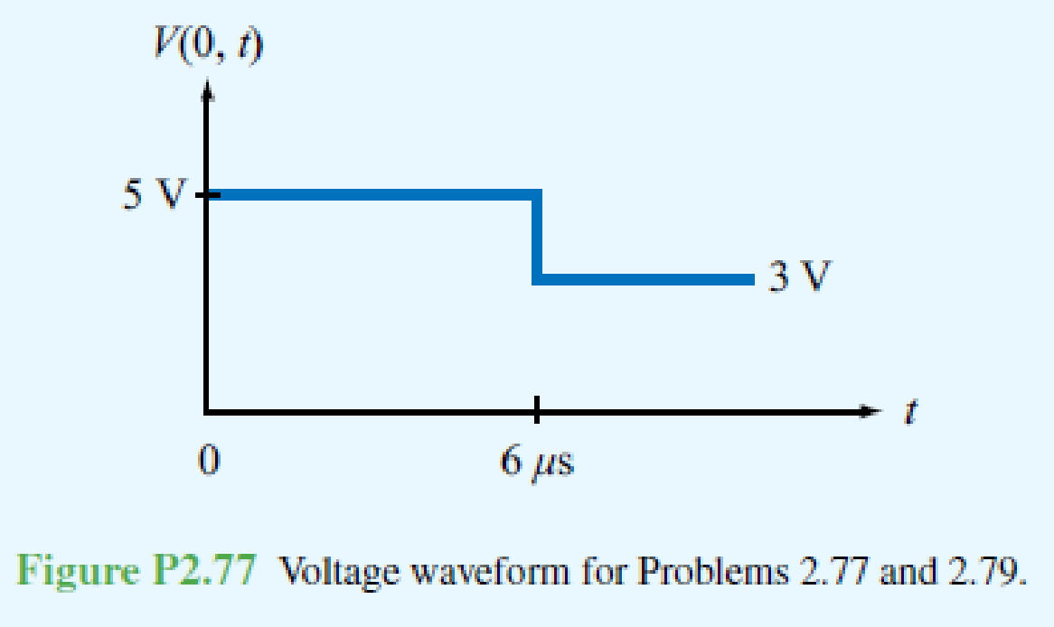
Suppose the voltage waveform shown in Fig. P2.77 was observed at the sending end of a 50 Ω transmission line in response to a step voltage introduced by a generator with Vg = 15 V and an unknown series resistance Rg. The line is 1 km in length, its velocity of propagation is 1 × 10⁸ m/s, and it is terminated in a load RL = 100 Ω.
- (a) Determine Rg.
- (b) Explain why the drop in level of V(0, t) at t = 6 μs cannot be due to reflection from the load.
- (c) Determine the shunt resistance Rf and location of the fault responsible for the observed waveform.
Expert Solution & Answer
Want to see the full answer?
Check out a sample textbook solution
Students have asked these similar questions
In the circuit shown, find the following:
1) The current Ix.
2) The average power dissipated in the capacitor.
3) The total average power dissipated in the two
resistors.
4) The average power of the independent voltage source
and specify whether it is supplied or absorbed.
5) The total impedance seen from the terminals of the
independent voltage source (Z=V/I).
20
-201
12/00V(+
21
www
202
2- If you have a unipolar winding stepper motor, draw the driver and the control circuit.
Note: The drawing is on paper.
Given the following reaction system, where Xo is the input, i.e u(t) = k₁ × Xo:
$Xo -> x1; k1*Xo
x2; k2*x1
x1
2 x2 ->%;
k3*x2^2
x2 ->;
k4*x2
Xo
1; k1 = 0.4
k2 4.5; k3 = 0.75
k4= 0.2
a) Build the model in Tellurium and run a simulation. Compute the Jacobian at steady
state using the method getFull Jacobian(). Make sure you are at steady state!
b) Write out the values for n and p
c) Write out the differential equations.
d) Write out the state space representation in terms of the rate constants etc.
e) Compute the values in the Jacobian matrix from d) by substituting the values of the rate
constants etc and any data you need from the simulation.
f) Confirm that the Jacobian you get in e) is the same as the one computed from the
simulation in a).
g) Is the system stable or not? If you find an eigenvalue of zero, that means the system is
marginally stable. You can get the eigenvalues using the tellurium method r.getFullEigenvalues()
Chapter 2 Solutions
Fundamentals of Applied Electromagnetics (7th Edition)
Ch. 2.2 - What is a transmission line? When should...Ch. 2.2 - Prob. 2CQCh. 2.2 - What constitutes a TEM transmission line?Ch. 2.2 - Prob. 4CQCh. 2.2 - Prob. 1ECh. 2.2 - Calculate the transmission line parameters at 1...Ch. 2.4 - Verify that Eq. (2.26a) indeed provides a solution...Ch. 2.4 - A two-wire air line has the following line...Ch. 2.6 - The attenuation constant represents ohmic losses....Ch. 2.6 - How is the wavelength of the wave traveling on...
Ch. 2.6 - Prob. 7CQCh. 2.6 - What is a standing-wave pattern? Why is its period...Ch. 2.6 - Prob. 9CQCh. 2.6 - For a lossless transmission line, = 20.7 cm at 1...Ch. 2.6 - A lossless transmission line uses a dielectric...Ch. 2.6 - Prob. 7ECh. 2.6 - Prob. 8ECh. 2.6 - Prob. 10ECh. 2.6 - A 140 lossless line is terminated in a load...Ch. 2.8 - What is the difference between the characteristic...Ch. 2.8 - What is a quarter-wave transformer? How can it be...Ch. 2.8 - Prob. 12CQCh. 2.8 - Prob. 13CQCh. 2.8 - if the input impedance of a lossless line is...Ch. 2.8 - Prob. 12ECh. 2.8 - A 300 feedline is to be connected to a 3 m long,...Ch. 2.9 - According to Eq. (2.102b), the instantaneous value...Ch. 2.9 - Prob. 16CQCh. 2.9 - What fraction of the incident power is delivered...Ch. 2.9 - Prob. 18CQCh. 2.9 - For a 50 lossless transmission line terminated in...Ch. 2.9 - For the line of Exercise 2-14, what is the...Ch. 2.10 - The outer perimeter of the Smith chart represents...Ch. 2.10 - What is an SWR circle? What quantities are...Ch. 2.10 - What line length corresponds to one complete...Ch. 2.10 - Which points on the SWR circle correspond to...Ch. 2.10 - Prob. 23CQCh. 2.10 - Use the Smith chart to find the values of ...Ch. 2.11 - Prob. 24CQCh. 2.11 - Prob. 25CQCh. 2.12 - What is transient analysis used for?Ch. 2.12 - Prob. 28CQCh. 2.12 - What is the difference between the bounce diagram...Ch. 2 - A transmission line of length l connects a load to...Ch. 2 - Show that the transmission-line model shown in...Ch. 2 - A 1 GHz parallel-plate transmission line consists...Ch. 2 - For the parallel-plate transmission line of...Ch. 2 - In addition to not dissipating power, a lossless...Ch. 2 - For a distortionless line [see Problem 2.13] with...Ch. 2 - Prob. 15PCh. 2 - A transmission line operating at 125 MHz has Z0 =...Ch. 2 - Prob. 17PCh. 2 - Polyethylene with r=2.25 is used as the insulating...Ch. 2 - Prob. 20PCh. 2 - Prob. 21PCh. 2 - Prob. 22PCh. 2 - Prob. 23PCh. 2 - A 50 lossless line terminated in a purely...Ch. 2 - Prob. 26PCh. 2 - Prob. 27PCh. 2 - Prob. 29PCh. 2 - Prob. 30PCh. 2 - Two half-wave dipole antennas, each with an...Ch. 2 - Prob. 34PCh. 2 - For the lossless transmission line circuit shown...Ch. 2 - A lossless transmission line is terminated in a...Ch. 2 - The input impedance of a 31 cm long lossless...Ch. 2 - FM broadcast station uses a 300 transmission line...Ch. 2 - A generator with Vg=300 V and Zg = 50 is...Ch. 2 - If the two-antenna configuration shown in Fig....Ch. 2 - For the circuit shown in Fig. P2.44, calculate the...Ch. 2 - The circuit shown in Fig. P2.45 consists of a 100 ...Ch. 2 - An antenna with a load impedance ZL=(75+j25) is...Ch. 2 - Prob. 47PCh. 2 - Use the Smith chart to determine the input...Ch. 2 - Prob. 52PCh. 2 - A lossless 50 transmission line is terminated in...Ch. 2 - A lossless 50 transmission line is terminated in...Ch. 2 - Use the Smith chart to find yL if zL = 1.5 j0.7.Ch. 2 - Prob. 59PCh. 2 - Prob. 62PCh. 2 - Determine Zin of the feed line shown in Fig....Ch. 2 - Prob. 73PCh. 2 - A 25 antenna is connected to a 75 lossless...Ch. 2 - Prob. 75PCh. 2 - Prob. 76PCh. 2 - Prob. 77PCh. 2 - In response to a step voltage, the voltage...Ch. 2 - Suppose the voltage waveform shown in Fig. P2.77...Ch. 2 - For the circuit of Problem 2.80, generate a bounce...Ch. 2 - In response to a step voltage, the voltage...
Knowledge Booster


Learn more about
Need a deep-dive on the concept behind this application? Look no further. Learn more about this topic, electrical-engineering and related others by exploring similar questions and additional content below.Similar questions
- Solve by Pen and Paper not using chatgpt or AIarrow_forwardYou just got a job at Shin-Etsu Chemical growing Si crystals with different dopants. Howmuch Ga needs to be added to 800 kg of Si melt to achieve a 5-10 Ω.cm (measured at midheight) Si CZ crystal with the following characteristics: height: 7 ft, width: 12 inchesdiameter. Assume, angular rotation 10 RPM, melt viscosity 0.1 poise, pull velocity 2mm/min.a. Generate a plot of the doping distribution throughout the length of the crystal (CGa vs. fs ).b. If a second crystal were to be pulled out of the melt without replenishment of silicon nordopant what would be the average resistivity of this crystal (or resistivity at mid height)arrow_forwardDO NOT USE AI OR CHAT GPT NEED HANDWRITTEN SOLUTIONarrow_forward
- 7. Complete the following problems for the circuit below. (a) When VDD = 120V, What is the voltage drop V1 across the 7Ω resistor? (b) If the voltage source VDD is set to obtain I1 = 2A, find the value of VDD. (c) If I1 = 100A, What is the value of I2arrow_forwarda) In terms of n and p, how many state variables and how many inputs can you see in the system below? dx1 =x12x2 + 9u1 dt dx2 =x1+x3+3u2 dt dx3 = 4x1 +5x2 - 12x3 dt b) Derive the state space representation for the above system c) Determine whether the system is stable or not.arrow_forwardCircuit Logic. Match each statement to the proper circuit. All circuits have been drawn with a light (L) to represent the load, whether it is a motor, bell, light, or any other load. In addition, each switch is illustrated as a pushbutton whether it is a maintained switch, momentary contact switch, pushbutton, switch-on target, or any other type of switch.arrow_forward
- a) In terms of n and p, how many state variables and how many inputs can you see in the system below? dx1 = 4x1 = x2 dt dx2 =-3x12x2 +U1 dt b) Derive the state space representation for the above system c) Determine whether the system is stable or not.arrow_forwardmatch each statement to the proper circuit. All circuits have been drawn with a light (L) to represent the load, whether it is a motor, bell, light or any other load. In addition, each switch is illustrated as a push button whether it is maintained switch, momentary contact switch, pushbutton, switch-on target, or any other type of switch.arrow_forwarda) In terms of n and p, how many state variables and how many inputs can you see in the system below? dx1 =-7x1 + x2 + 5u1 dt dx2 =-11x1+x3 + 2u1 dt dx3 = -8x16u1 dt b) Derive the state space representation for the above system c) Determine whether the system is stable or not.arrow_forward
- Question 2 (20 points) a) In terms of n and p, how many state variables and how many inputs can you see in the system below? dx1 dt =x1- 2x2 dx2 = 3x1 - 4x2 dt b) Derive the state space representation for the above system c) Determine whether the system is stable or not.arrow_forwardStuck on the question. Please do not use AI, it will get the answer wrong.arrow_forwardConsider a particle confined in an infinite potential well as shown below and its wave function Solve the following problems. is derived as √(x) = A sin (TA), and energy E= H U 0 U=0 a x πλη 2ma² €30 (iii) Calculate the value of A. [Hint: The probability of finding the particle in 0arrow_forwardarrow_back_iosSEE MORE QUESTIONSarrow_forward_ios
Recommended textbooks for you
 Power System Analysis and Design (MindTap Course ...Electrical EngineeringISBN:9781305632134Author:J. Duncan Glover, Thomas Overbye, Mulukutla S. SarmaPublisher:Cengage Learning
Power System Analysis and Design (MindTap Course ...
Electrical Engineering
ISBN:9781305632134
Author:J. Duncan Glover, Thomas Overbye, Mulukutla S. Sarma
Publisher:Cengage Learning
How do Electric Transmission Lines Work?; Author: Practical Engineering;https://www.youtube.com/watch?v=qjY31x0m3d8;License: Standard Youtube License