
Electronics Fundamentals: Circuits, Devices & Applications
8th Edition
ISBN: 9780135072950
Author: Thomas L. Floyd, David Buchla
Publisher: Prentice Hall
expand_more
expand_more
format_list_bulleted
Concept explainers
Videos
Textbook Question
Chapter 2, Problem 32P
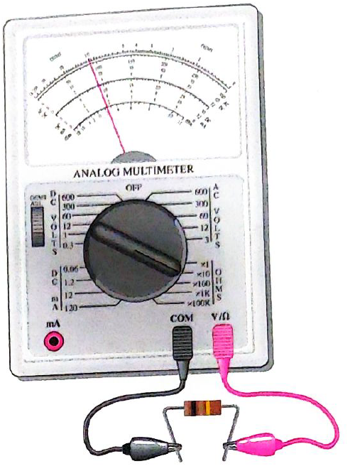
How much resistance is the meter in Figure 2-66 measuring?
Expert Solution & Answer
Want to see the full answer?
Check out a sample textbook solution
Students have asked these similar questions
Please solve this question step by step and handwritten and do not use chat gpt or ai tools thank you very much!
Please solve question c,d,e step by step and handwritten and do not use chat gpt or ai tools thank you very much!
Q1: Design a logic circuit for the finite-state machine described by the assigned
table in Fig. 1:
Using D flip-flops.
a.
b.
Using T flip-flops.
Present
Next State
Output
State
x=0
x=0
YE
Y₁Y
Y₁Y
Z
00
00
01
0
0
от
00
0
0
10
00
10
11
00
10
0
Chapter 2 Solutions
Electronics Fundamentals: Circuits, Devices & Applications
Ch. 2 - The number of neutrons in the nucleus is the...Ch. 2 - The unit of charge is the ampere.Ch. 2 - Energy in a battery is stored in the form of...Ch. 2 - Prob. 4TFQCh. 2 - In a five-band precision resistor, the fourth band...Ch. 2 - A rheostat performs the same function as a...Ch. 2 - A strain gauge changes resistance in response to...Ch. 2 - Prob. 8TFQCh. 2 - Prob. 9TFQCh. 2 - The three basic measurements that can be done by a...
Ch. 2 - A neutral atom with an atomic number of three has...Ch. 2 - Electron orbits are called shells nuclei waves...Ch. 2 - Materials in which current cannot be established...Ch. 2 - When placed close together, a positively charged...Ch. 2 - The charge on a single electron is 6.2510-18C...Ch. 2 - Prob. 6STCh. 2 - Prob. 7STCh. 2 - Prob. 8STCh. 2 - Prob. 9STCh. 2 - Prob. 10STCh. 2 - Prob. 11STCh. 2 - There is no current in a circuit when a series...Ch. 2 - Prob. 13STCh. 2 - Potentiometers and rheostats are types of voltage...Ch. 2 - The current in a given circuit is not to exceed 22...Ch. 2 - How many coulombs of charge do 501031 electrons...Ch. 2 - How many electrons does it take to make 80C of...Ch. 2 - What is the charge in coulombs of the nucleus of a...Ch. 2 - What is the charge in coulombs of the nucleus of a...Ch. 2 - Detemine the voltage in each of the following...Ch. 2 - Five hundred joules of energy are used to move 100...Ch. 2 - What is the voltage of a battery that uses 800 J...Ch. 2 - How much energy does a 12 V battery in your car...Ch. 2 - Assume that a solar battery charger delivers 2.5 J...Ch. 2 - If the solar cell in Problem 9 has moved the...Ch. 2 - Determine the current in each of the following...Ch. 2 - Six-tenths coulomb passes a point in 3 s. What is...Ch. 2 - How long does it take 10 C to flow past a point if...Ch. 2 - How many coulombs pass a point in 0.1 s when the...Ch. 2 - Figure 2-61(a) shows color-coded resistors....Ch. 2 - 16. Find the minimum and the maximum resistance...Ch. 2 - If you need a 270 resistor with 5% tolerance. what...Ch. 2 - Determine the resistance value and tolerance for...Ch. 2 - Determine the resitance and tolerance of each of...Ch. 2 - Determine the color bands for each of the...Ch. 2 - Determine the resistance and tolerance of each of...Ch. 2 - Determine the color bands for each of the...Ch. 2 - Determine the resistance values represented by the...Ch. 2 - The adjustable contact of a linear potentlometer...Ch. 2 - Trace the current path in the lamp circuit of...Ch. 2 - With the switch in either position, redraw the...Ch. 2 - Show the placement of an ammeter and a voltmeter...Ch. 2 - Show how you would measure the resistance of R2 in...Ch. 2 - In Figure 2-64 what does each voltmeter indicate...Ch. 2 - In Figure 2-64, show how to connect an ammeter to...Ch. 2 - What is the voltage reading of the meter in Figure...Ch. 2 - How much resistance is the meter in Figure 2-66...Ch. 2 - Determine the resistance indicated by each of the...Ch. 2 - A multimeter has the following ranges:...Ch. 2 - A resistor with a current of 2 A through it in an...Ch. 2 - If 5741015 electrons flow through a speaker wire...Ch. 2 - A 120 V source is to be connected to a 1500...Ch. 2 - Determine the resistance and tolerance of each...Ch. 2 - Prob. 39PCh. 2 - Through which resistor in Figure 2-70 is there...Ch. 2 - In Figure 2-70, show the proper placement of...Ch. 2 - Show the proper placement of voltmeters to measure...Ch. 2 - Devise a switch arrangement where by two voltage...
Knowledge Booster


Learn more about
Need a deep-dive on the concept behind this application? Look no further. Learn more about this topic, electrical-engineering and related others by exploring similar questions and additional content below.Similar questions
- 2. Using the approximate method, hand sketch the Bode plot for the following transfer functions. a) H(s) = 10 b) H(s) (s+1) c) H(s): = 1 = +1 100 1000 (s+1) 10(s+1) d) H(s) = (s+100) (180+1)arrow_forwardQ4: Write VHDL code to implement the finite-state machine described by the state Diagram in Fig. 1. Fig. 1arrow_forward1. Consider the following feedback system. Bode plot of G(s) is shown below. Phase (deg) Magnitude (dB) -50 -100 -150 -200 0 -90 -180 -270 101 System: sys Frequency (rad/s): 0.117 Magnitude (dB): -74 10° K G(s) Bode Diagram System: sys Frequency (rad/s): 36.8 Magnitude (dB): -99.7 System: sys Frequency (rad/s): 20 Magnitude (dB): -89.9 System: sys Frequency (rad/s): 20 Phase (deg): -143 System: sys Frequency (rad/s): 36.8 Phase (deg): -180 101 Frequency (rad/s) a) Determine the range of K for which the closed-loop system is stable. 102 10³ b) If we want the gain margin to be exactly 50 dB, what is value for K we should choose? c) If we want the phase margin to be exactly 37°, what is value of K we should choose? What will be the corresponding rise time (T) for step-input? d) If we want steady-state error of step input to be 0.6, what is value of K we should choose?arrow_forward
- : Write VHDL code to implement the finite-state machine/described by the state Diagram in Fig. 4. X=1 X=0 solo X=1 X=0 $1/1 X=0 X=1 X=1 52/2 $3/3 X=1 Fig. 4 X=1 X=1 56/6 $5/5 X=1 54/4 X=0 X-O X=O 5=0 57/7arrow_forwardQuestions: Q1: Verify that the average power generated equals the average power absorbed using the simulated values in Table 7-2. Q2: Verify that the reactive power generated equals the reactive power absorbed using the simulated values in Table 7-2. Q3: Why it is important to correct the power factor of a load? Q4: Find the ideal value of the capacitor theoretically that will result in unity power factor. Vs pp (V) VRIPP (V) VRLC PP (V) AT (μs) T (us) 8° pf Simulated 14 8.523 7.84 84.850 1000 29.88 0.866 Measured 14 8.523 7.854 82.94 1000 29.85 0.86733 Table 7-2 Power Calculations Pvs (mW) Qvs (mVAR) PRI (MW) Pay (mW) Qt (mVAR) Qc (mYAR) Simulated -12.93 -7.428 9.081 3.855 12.27 -4.84 Calculated -12.936 -7.434 9.083 3.856 12.32 -4.85 Part II: Power Factor Correction Table 7-3 Power Factor Correction AT (us) 0° pf Simulated 0 0 1 Measured 0 0 1arrow_forwardQuestions: Q1: Verify that the average power generated equals the average power absorbed using the simulated values in Table 7-2. Q2: Verify that the reactive power generated equals the reactive power absorbed using the simulated values in Table 7-2. Q3: Why it is important to correct the power factor of a load? Q4: Find the ideal value of the capacitor theoretically that will result in unity power factor. Vs pp (V) VRIPP (V) VRLC PP (V) AT (μs) T (us) 8° pf Simulated 14 8.523 7.84 84.850 1000 29.88 0.866 Measured 14 8.523 7.854 82.94 1000 29.85 0.86733 Table 7-2 Power Calculations Pvs (mW) Qvs (mVAR) PRI (MW) Pay (mW) Qt (mVAR) Qc (mYAR) Simulated -12.93 -7.428 9.081 3.855 12.27 -4.84 Calculated -12.936 -7.434 9.083 3.856 12.32 -4.85 Part II: Power Factor Correction Table 7-3 Power Factor Correction AT (us) 0° pf Simulated 0 0 1 Measured 0 0 1arrow_forward
- electric plants. Prepare the load schedulearrow_forwardelectric plants Draw the column diagram. Calculate the voltage drop. by hand writingarrow_forwardelectric plants. Draw the lighting, socket, telephone, TV, and doorbell installations on the given single-story project with an architectural plan by hand writingarrow_forward
arrow_back_ios
SEE MORE QUESTIONS
arrow_forward_ios
Recommended textbooks for you
 Electricity for Refrigeration, Heating, and Air C...Mechanical EngineeringISBN:9781337399128Author:Russell E. SmithPublisher:Cengage Learning
 EBK ELECTRICAL WIRING RESIDENTIALElectrical EngineeringISBN:9781337516549Author:SimmonsPublisher:CENGAGE LEARNING - CONSIGNMENT
 Delmar's Standard Textbook Of ElectricityElectrical EngineeringISBN:9781337900348Author:Stephen L. HermanPublisher:Cengage Learning
Electricity for Refrigeration, Heating, and Air C...
Mechanical Engineering
ISBN:9781337399128
Author:Russell E. Smith
Publisher:Cengage Learning
EBK ELECTRICAL WIRING RESIDENTIAL
Electrical Engineering
ISBN:9781337516549
Author:Simmons
Publisher:CENGAGE LEARNING - CONSIGNMENT
Delmar's Standard Textbook Of Electricity
Electrical Engineering
ISBN:9781337900348
Author:Stephen L. Herman
Publisher:Cengage Learning
Star Delta Starter Explained - Working Principle; Author: The Engineering Mindset;https://www.youtube.com/watch?v=h89TTwlNnpY;License: Standard Youtube License