
Videos
Pipe 2 has been inserted snugly into Pipe I. but the holes Tor a connecting pin do not line up; there is a gap s. The user decides to apply either force P:lo Pipe I or force P-, to Pipe 2, whichever is smaller. Determine the following using the numerical properties in the box.
(a) If only P{is applied, find Pt{tips} required to close gap s; if a pin is then inserted and Ptremoved, what are reaction forces RAand RBfor this load case?
(b) If only P2is applied, find P2{kips) required to close gap a; if a pin is inserted and P2removed, what are reaction forces R^ and RBfor this load case?
(c) What is the maximum shear stress in the pipes, for the loads in parts (a) and (b)?
(d) If a temperature increase IT is to be applied to the entire structure to close gaps{instead of applying forces Ptand P2), find the AT required to close the gap. If a pin is inserted after the gaphas closed, what are reaction forces .''.', and RBfor this case? (e) Finally, if the structure (with pin inserted) then cools to the original ambient temperature, what are reaction forces Rtand P 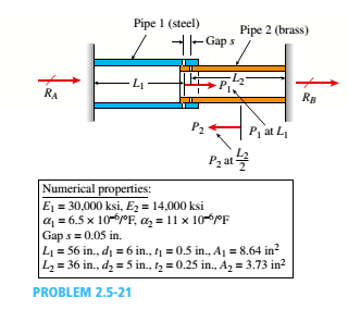
(a)
The reactions at A and B.
Answer to Problem 2.5.21P
The reaction at A is =
The reaction at B is =
Explanation of Solution
Given information:
The gap between the pipes is
Write the expression for elongation in pipe 1.
Here, length of pipe 1 is
Write the expression for elongation at point B.
Here, elongation at point B is
Write the expression for net elongation at B.
Here, elongation at point 1 is
Substitute
Write the reaction at point A.
Here, reaction at A is
Calculation:
Substitute
The force required to close the gap is
Substitute
Substitute
Conclusion:
The reaction at A is
The reaction at B is
(b)
The reaction at A is
The reaction at B is
Answer to Problem 2.5.21P
The reaction at A is
The reaction at B is
Explanation of Solution
Given information:
The gap between the pipes is
Write the expression for force applied at pipe 2.
Here, force applied at pipe 2 is
Calculation:
Substitute
Substitute
Substitute
Conclusion:
The reaction at A is
The reaction at B is
(b)
The maximum shear stress in pipe 1 and pipe 2.
.
Answer to Problem 2.5.21P
The maximum shear stress in pipe 1 is
The maximum shear stress in pipe 2 is
Explanation of Solution
Given information:
The gap between the pipes is
Write the expression for maximum shear stress in pipe 1.
Here, maximum shear stress in pipe 1 is
Write the expression for maximum shear stress in pipe.
Here, maximum shear stress in pipe 2 is
Calculation:
Substitute
The maximum shear stress in pipe 1 is =
Substitute
Conclusion:
The maximum shear stress in pipe 1 is =
The maximum shear stress in pipe 2 is =
(d)
The rise in temperature required to close the gap.
The reactions.
Answer to Problem 2.5.21P
The rise in temperature required to close the gap is
The reactions are
Explanation of Solution
Given information:
The gap between the pipes is
Write the expression for temperature raise.
Here, raise in temperature is
Calculation:
Substitute
Since the temperature remains constant, so the reactions are zero.
Conclusion:
The temperature raise required to close the gap is
The reactions are
(e)
The reaction at A.
The reaction at B.
Answer to Problem 2.5.21P
The reaction at A is
The reaction at B is
Explanation of Solution
Given information:
The gap between the pipes is
Calculation:
Substitute
Substitute
Conclusion:
The reaction at A is =
The reaction at B is =
Want to see more full solutions like this?
Chapter 2 Solutions
Bundle: Mechanics Of Materials, Loose-leaf Version, 9th + Mindtap Engineering, 2 Terms (12 Months) Printed Access Card


- Prob 3. The triangular plate is fixed at its base, and its apex A is given a horizontal displacement of 5 mm. Determine the shear strain, Yxy, at A. Prob 4. The triangular plate is fixed at its base, and its apex A is given a horizontal displacement of 5 mm. Determine the average normal strain & along the x axis. Prob 5. The triangular plate is fixed at its base, and its apex A is given a horizontal displacement of 5 mm. Determine the average normal strain &x along the x' axis. x' 45° 800 mm 45° 45% 800 mm 5 mmarrow_forwardAn airplane lands on the straight runaway, originally travelling at 110 ft/s when s = 0. If it is subjected to the decelerations shown, determine the time t' needed to stop the plane and construct the s -t graph for the motion. draw a graph and show all work step by steparrow_forwarddny dn-1y dn-1u dn-24 +a1 + + Any = bi +b₂- + +bnu. dtn dtn-1 dtn-1 dtn-2 a) Let be a root of the characteristic equation 1 sn+a1sn- + +an = : 0. Show that if u(t) = 0, the differential equation has the solution y(t) = e\t. b) Let к be a zero of the polynomial b(s) = b₁s-1+b2sn−2+ Show that if the input is u(t) equation that is identically zero. = .. +bn. ekt, then there is a solution to the differentialarrow_forward
- B 60 ft WAB AB 30% : The crane's telescopic boom rotates with the angular velocity w = 0.06 rad/s and angular acceleration a = 0.07 rad/s². At the same instant, the boom is extending with a constant speed of 0.8 ft/s, measured relative to the boom. Determine the magnitude of the acceleration of point B at this instant.arrow_forwardThe motion of peg P is constrained by the lemniscate curved slot in OB and by the slotted arm OA. (Figure 1) If OA rotates counterclockwise with a constant angular velocity of 0 = 3 rad/s, determine the magnitude of the velocity of peg P at 0 = 30°. Express your answer to three significant figures and include the appropriate units. Determine the magnitude of the acceleration of peg P at 0 = 30°. Express your answer to three significant figures and include the appropriate units. 0 (4 cos 2 0)m² B Aarrow_forward5: The structure shown was designed to support a30-kN load. It consists of a boom AB with a 30 x 50-mmrectangular cross section and a rod BC with a 20-mm-diametercircular cross section. The boom and the rod are connected bya pin at B and are supported by pins and brackets at A and C,respectively.1. Calculate the normal stress in boom AB and rod BC,indicate if in tension or compression.2. Calculate the shear stress of pins at A, B and C.3. Calculate the bearing stresses at A in member AB,and in the bracket.arrow_forward
- 4: The boom AC is a 4-in. square steel tube with a wallthickness of 0.25 in. The boom is supported by the 0.5-in.-diameter pinat A, and the 0.375-in.-diameter cable BC. The working stresses are 25ksi for the cable, 18 ksi for the boom, and 13.6 ksi for shear in the pin.Neglect the weight of the boom.1. Calculate the maximum value of P (kips) based on boom compression and the maximum value of P (kips) based on tension in the cable.2. Calculate the maximum value of P (kips) based on shear in pin.arrow_forward3: A steel strut S serving as a brace for a boat hoist transmits a compressive force P = 54 kN to the deck of a pier as shown in Fig. STR-08. The strut has a hollow square cross section with a wall thickness t =12mm and the angle θ between the strut and the horizontal is 40°. A pin through the strut transmits the compressive force from the strut to two gusset plates G that are welded to the base plate B. Four anchor bolts fasten the base plate to the deck. The diameter of the pin is 20mm, the thickness of the gusset plates is 16mm, the thickness of the base plate is 8mm, and the diameter of the anchor bolts is 12mm. Disregard any friction between the base plate and the deck.1. Determine the shear stress in the pin, in MPa and the shear stress in the anchor bolts, in MPa.2. Determine the bearing stress in the strut holes, in MPa.arrow_forward1. In the figure, the beam, W410x67, with 9 mm web thicknesssubjects the girder, W530x109 with 12 mm web thickness to a shear load,P (kN). 2L – 90 mm × 90 mm × 6 mm with bolts frame the beam to thegirder.Given: S1 = S2 = S5 = 40 mm; S3 = 75 mm; S4 = 110 mmAllowable Stresses are as follows:Bolt shear stress, Fv = 125 MPaBolt bearing stress, Fp = 510 MPa1. Determine the allowable load, P (kN), based on the shearcapacity of the 4 – 25 mm diameter bolts (4 – d1) and calculate the allowable load, P (kN), based on bolt bearing stress on the web of the beam.2. If P = 450 kN, determine the minimum diameter (mm) of 4 – d1based on allowable bolt shear stress and bearing stress of thebeam web.arrow_forward
- 6: The 6-kN load P is supported by two wooden members of 75 x 125-mm uniform cross section that are joined by the simple glued scarf splice shown.1. Calculate the normal stress in the glue, in MPa.2. Calculate the shear stress in the glue, in MPa.arrow_forwardUsing Matlab calculate the following performance characteristics for a Tesla Model S undergoing the 4506 drive cycle test Prated Trated Ebat 80kW 254 Nm 85kWh/1645kg MUEH A rwheel 0.315M 133.3 C 0.491 Ng ng 7g 8.190.315 8.19 0.315 7ed= 85% Ebpt 35-956 DRIVE AXLE Ebfb chę =85% V Minverter H/A Battery Charger En AC Pry 9) required energy output from the motor to drive this cycle Cassume no regenerative braking) b) range of the Tesla Model S for this drive cycle (assume no regenerative breaking c) estimated mpge cycle of the Tesla Model S for this drive Cassume no regenerative breaking) d) Recalculate parts abc now assuming you can regenerate returns correctly due to inefficiency. from braking. Be careful to handle the diminishing energy braking makes in terms of required e) Quantify the percentage difference that regenerative required energy, range and mpge, DI L Ta a ra OLarrow_forwardHW.5.1 Determine the vertical displacement of joint C on the truss as shown by using Castigliano's theorem. Let E = 200(109) GPa and A = 300 mm² 4 m E 20 kN 3 m 3 m B D 30 kN Carrow_forward
 Mechanics of Materials (MindTap Course List)Mechanical EngineeringISBN:9781337093347Author:Barry J. Goodno, James M. GerePublisher:Cengage Learning