
EP ELECTRICAL ENGR.-MODIF.MASTERINGENGR
7th Edition
ISBN: 9780134486994
Author: HAMBLEY
Publisher: PEARSON CO
expand_more
expand_more
format_list_bulleted
Concept explainers
Videos
Textbook Question
Chapter 2, Problem 2.51P
Given
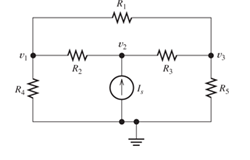
Figure P2.51
Expert Solution & Answer
Want to see the full answer?
Check out a sample textbook solution
Students have asked these similar questions
Don't use ai to answer I will report you answer
A three-phase transmission line supplies power to three loads at a voltage
408 Vrms (line to line). The loads are as follows:
Load 1:
S₁ = 100+ j50 VA
Load 2:
S₂ = 40-j20 VA
Load 3:
S3 = 10 + j0 VA
Find the magnitude of the line current | Line and the combined power factor of
the loads.
Hint:
Steral \= √3 | Vime |× | Ime |
line
line
Can you show why the answer to this question R = 199 ohm?
Chapter 2 Solutions
EP ELECTRICAL ENGR.-MODIF.MASTERINGENGR
Ch. 2 - Reduce each of the networks shown in Figure P2.1...Ch. 2 - A 4- resistance is in series with the parallel...Ch. 2 - Find the equivalent resistance looking into...Ch. 2 - Suppose that we need a resistance of 1.5 k and...Ch. 2 - Find the equivalent resistance between terminals a...Ch. 2 - Find the equivalent resistance between terminals a...Ch. 2 - What resistance in parallel with 120 results in...Ch. 2 - Determine the resistance between terminals a and b...Ch. 2 - Two resistances having values of R and 2R are in...Ch. 2 - A network connected between terminals a and b...
Ch. 2 - Two resistances R1 and R2 are connected in...Ch. 2 - Find the equivalent resistance for the infinite...Ch. 2 - If we connect n 1000- resistances in parallel,...Ch. 2 - The heating element of an electric cook top has...Ch. 2 - We are designing an electric space heater to...Ch. 2 - Sometimes, we can use symmetry considerations to...Ch. 2 - The equivalent resistance between terminals a and...Ch. 2 - Three conductances G1 G2, and G3 are in series....Ch. 2 - Most sources of electrical power behave as...Ch. 2 - The resistance for the network shown in Figure...Ch. 2 - Often, we encounter delta-connected loads such as...Ch. 2 - What are the steps in solving a circuit by network...Ch. 2 - Find the values of i1 and i2 in Figure P2.23....Ch. 2 - Find the voltages v1 and v2 for the circuit shown...Ch. 2 - Find the values of v and i in Figure P2.25. Figure...Ch. 2 - Consider the circuit shown in Figure P2.24....Ch. 2 - Find the voltage v and the currents i1 and 12 for...Ch. 2 - Find the values of vs, v1, and i2 in Figure P2.28....Ch. 2 - Find the values of i1 and i2 in Figure P2.29....Ch. 2 - Consider the cirrcuit shown in Figure P2.30 Find...Ch. 2 - Solve for the values of i1, i2, and the powers for...Ch. 2 - The 12-V source in Figure P2.32 is delivering 36...Ch. 2 - Refer to the circuit shown in Figure P2.33. With...Ch. 2 - Find the values of i1 and i2 in Figure P2.34. Find...Ch. 2 - Find the values of i1 and i2 in Figure P2.35...Ch. 2 - Use the voltage-division principle to calculate...Ch. 2 - Use the current-division principle to calculate i1...Ch. 2 - Use the voltage-division principle to calculate...Ch. 2 - Use the current-division principle to calculate...Ch. 2 - Suppose we need to design a voltage-divider...Ch. 2 - A source supplies 120 V to the series combination...Ch. 2 - We have a 60- resistance, a 20- resistance, and...Ch. 2 - A worker is standing on a wet concrete floor,...Ch. 2 - Suppose we have a load that absorbs power and...Ch. 2 - We have a load resistance of 50 that we wish to...Ch. 2 - We have a load resistance of 1 k that we wish to...Ch. 2 - The circuit of Figure P2.47 is similar to networks...Ch. 2 - Write equations and solve for the node voltages...Ch. 2 - Solve for the node voltages shown in Figure P2.49....Ch. 2 - Solve for the node voltages shown in Figure P2.50....Ch. 2 - Given R1=4 , R2=5 , R2=8 , R4=10 , R5=2 , and...Ch. 2 - Determine the value of i1 in Figure P2.52 using...Ch. 2 - Given R1=15 , R5=5 , R3=20 , R4=10 , R5=8 , R6=4 ,...Ch. 2 - In solving a network, what rule must you observe...Ch. 2 - Use the symbolic features of MATLAB to find an...Ch. 2 - Solve for the values of the node voltages shown in...Ch. 2 - Solve for the node voltages shown in Figure P2.57....Ch. 2 - Solve for the power delivered to the 8- ...Ch. 2 - Solve for the node voltages shown in Figure P2.59....Ch. 2 - Find the equivalent resistance looking into...Ch. 2 - Find the equivalent resistance looking into...Ch. 2 - Figure P2.62 shows an unusual voltage-divider...Ch. 2 - Solve for the node voltages in the circuit of...Ch. 2 - We have a cube with 1- resistances along each...Ch. 2 - Solve for the power delivered to the 15- resistor...Ch. 2 - Determine the value of v2 and the power delivered...Ch. 2 - Use mesh-current analysis to find the value of i1...Ch. 2 - Solve for the power delivered by the voltage...Ch. 2 - Use mesh-current analysis to find the value of v...Ch. 2 - Use mesh-current analysis to find the value of i3...Ch. 2 - Use mesh-current analysis to find the values of i1...Ch. 2 - Find the power delivered by the source and the...Ch. 2 - Use mesh-current analysis to find the values of i1...Ch. 2 - Use mesh-current analysis to find the values of i1...Ch. 2 - The circuit shown in Figure P2.75 is the dc...Ch. 2 - Use MATLAB and mesh-current analysis to determine...Ch. 2 - Connect a 1-V voltage source across terminals a...Ch. 2 - Connect a 1-V voltage source across the terminals...Ch. 2 - Use MATLAB to solve for the mesh currents in...Ch. 2 - Find the Thévenin and Norton equivalent circuits...Ch. 2 - We can model a certain battery as a voltage source...Ch. 2 - Find the Thévenin and Norton equivalent circuits...Ch. 2 - Find the Thévenin and Norton equivalent circuits...Ch. 2 - Find the Thévenin arid Norton equivalent circuits...Ch. 2 - An automotive battery has an open-circuit voltage...Ch. 2 - A certain two-terminal circuit has an open-circuit...Ch. 2 - If we measure the voltage at the terminals of a...Ch. 2 - Find the Thévenin and Norton equivalent circuits...Ch. 2 - Find the maximum power that can be delivered to a...Ch. 2 - Find the maximum power that can be delivered to a...Ch. 2 - Figure P2.91 shows a resistive load RL connected...Ch. 2 - Starling from the Norton equivalent circuit with a...Ch. 2 - A battery can be modeled by a voltage source Vt in...Ch. 2 - Use superposition to find the current i in Figure...Ch. 2 - Solve for is in Figure P2.49 by using...Ch. 2 - Solve the circuit shown in Figure P2.48 by using...Ch. 2 - Solve for i1 in Figure P2.34 by using...Ch. 2 - Another method of solving the circuit of Figure...Ch. 2 - Use the method of Problem P2.98 for the circuit of...Ch. 2 - Solve for the actual value of i6 for the circuit...Ch. 2 - Device A shown in Figure P2.101 has v=3i2 for i 0...Ch. 2 - The Wheatstone bridge shown in Figure 2.66 is...Ch. 2 - The Wheatstone bridge shown in Figure 2.66has...Ch. 2 - In theory, any values can be used for R1 and R3 in...Ch. 2 - Derive expressions for the Thévenin voltage and...Ch. 2 - Derive Equation 2.93 for the bridge circuit of...Ch. 2 - Prob. 2.107PCh. 2 - Explain what would happen if, in wiring the bridge...Ch. 2 - Match each entry in Table T2.1(a) with the best...Ch. 2 - Consider the circuit of Figure T2.2 with vs=96V ,...Ch. 2 - Write MATLAB code to solve for the node voltages...Ch. 2 - Write a set of equations that can be used to solve...Ch. 2 - Determine the Thévenin and Norton equivalent...Ch. 2 - According to the superposition principle, what...Ch. 2 - Determine the equivalent resistance between...Ch. 2 - Transform the 2-A current source and 6- ...
Knowledge Booster


Learn more about
Need a deep-dive on the concept behind this application? Look no further. Learn more about this topic, electrical-engineering and related others by exploring similar questions and additional content below.Similar questions
- 2.5. Find the half-power beamwidth (HPBW) and first-null beamwidth (FNBW), in radians and degrees, for the following normalized radiation intensities: (a) U(9) cos θ cos(20) (b) U(θ)-cos2 θ cos2(26) (c) U(θ) = cos(θ) cos(30) (0 < θ < 900,0 < φ 360) (d) U(t) = cos2(9) cos2(39) (e) U(9) = cos(29) cos(39) (f) U (ecos (20) cos (30)arrow_forwardDon't use ai to answer I will report you answerarrow_forwardDon't use ai to answer I will report you answerarrow_forward
- A 60 Hz, 230 kV, 275 km long, uncompensated three-phase transmission line consists of three conductors bundled by phase, such that each conductor in the line is of the ACSR Falcon type. The separation between each bundled conductor is d = 45 cm and the separation between each phase of the line is 2.4 m. Calculate: "The parameters R, L, C of the line in Q2/km; µH/m and nF/m. And the total values of ZL and YC in Q and S, respectively, and in polar coordinates." Generalized constants A, B, C and D of the line, according to the type of transmission line. Present the results in rectangular coordinates. If a three-phase wye load draws 3/4 of the nominal current of the 300 MW system with FP = 0.85 lagging and at 230 kV, calculate: (a) Current at the load in KA (b) Voltage at the source in KV, (c) Current at the source in kA and (d) power at the source in MVA. Obtain the results per phase. Transmission line voltage regulation percentagearrow_forwardDetermine the required EMT size for the following combination of conductors:18. Four 8 AWG Type THW and four 12 AWG Type THW:19. Three 350 kcmil and one 250 kcmil Type XHHW conductors and a 4 AWG bare conductor:20. In a nonmetallic-sheathed (Type NM) cable installation, a 10⁄3 with equipmentgrounding conductor is installed in a metal octagonal box to supply two 12⁄2 withequipment grounding conductor branch-circuit cables. What is the minimum sizebox? The box contains internal cable clampsarrow_forwardFor problems 8 and 9, determine the correct box size for each of the following conditions:8. Two nonmetallic sheathed cables with two 12 AWG conductors, an equipment groundingconductor, and a switch in a metal box without a plaster ring.9. A raceway run serving a series of luminaires, connected to a total of three circuits. Theluminaires are supplied by 120 volts from a 3-phase, 4-wire system. Each box will containtwo circuits running through the box and a third circuit connected to a luminaire, which issupported by a luminaire stud in the box. Use 12 AWG Type THHN conductors.arrow_forward
- 28. The minimum size raceway for the following conductors is: a. Three, 250 kcmil conductors with XHHW insulation b. One, 3⁄0 AWG conductor with XHHW insulation c. One, 4 AWG conductor with XHHW insulation29. The minimum size raceway for the following conductors is: a. Twelve, 6 AWG conductors with THHN insulation b. Nine, 8 AWG conductors with THHN insulation c. Eighteen, 10 AWG conductor with THHN insulation d. One, 10 AWG equipment grounding conductor with THHN insulation30. The minimum size wireway for the following with parallel conductors is: a. Two sets of three, 250 kcmil conductors with XHHW insulation b. Two, 3⁄0 AWG conductors with XHHW insulation c. 1, 4 AWG conductor with XHHW insulation d. The conductors terminate on three power distribution blocks. Each one has adimension of 4 in. wide and 3 in. high:arrow_forwardbox fill calculationsarrow_forwardTwo trade size 3 raceways enter a pull box directly across from each other. No other raceways enter the box. What are the minimum dimensions of the box?11. Length ______________________12. Width ______________________13. Depth ______________________Two trade size 3 raceways enter a pull box at right angles to each other. No other racewaysenter the box. What are the minimum dimensions of the box?14. Length ______________________15. Width ______________________16. Depth ______________________arrow_forward
- not use ai pleasearrow_forwardFor Questions 21, 22, and 23, two 3-in. raceways enter a pull box, one through a side and theother in the back. Four 500 kcmil, type THHN conductors will be installed in the raceway.No other raceways enter the box. What are the minimum dimensions of the pull box 21. Length ________________22. Width ________________23. Depth ________________arrow_forwardFor Questions 24, 25, 26, and 27, determine the answers using the information shown in the drawing. Trade size 2 conduit Trade size 2 conduit Trade size 3 conduit Trade size 3 conduit Trade size 2 conduit Trade size 2 conduit 24. Dimension a must be at least. 25. Dimension b must be at least the same conductors). inches. inches (the raceways contain inches. 26. Dimension c must be at least 27. Do you foresee any difficulties in installing the conductors in these raceways? Explain.arrow_forward
arrow_back_ios
SEE MORE QUESTIONS
arrow_forward_ios
Recommended textbooks for you
 Introductory Circuit Analysis (13th Edition)Electrical EngineeringISBN:9780133923605Author:Robert L. BoylestadPublisher:PEARSON
 Delmar's Standard Textbook Of ElectricityElectrical EngineeringISBN:9781337900348Author:Stephen L. HermanPublisher:Cengage Learning
 Programmable Logic ControllersElectrical EngineeringISBN:9780073373843Author:Frank D. PetruzellaPublisher:McGraw-Hill Education
 Fundamentals of Electric CircuitsElectrical EngineeringISBN:9780078028229Author:Charles K Alexander, Matthew SadikuPublisher:McGraw-Hill Education
 Electric Circuits. (11th Edition)Electrical EngineeringISBN:9780134746968Author:James W. Nilsson, Susan RiedelPublisher:PEARSON
 Engineering ElectromagneticsElectrical EngineeringISBN:9780078028151Author:Hayt, William H. (william Hart), Jr, BUCK, John A.Publisher:Mcgraw-hill Education,
Introductory Circuit Analysis (13th Edition)
Electrical Engineering
ISBN:9780133923605
Author:Robert L. Boylestad
Publisher:PEARSON
Delmar's Standard Textbook Of Electricity
Electrical Engineering
ISBN:9781337900348
Author:Stephen L. Herman
Publisher:Cengage Learning
Programmable Logic Controllers
Electrical Engineering
ISBN:9780073373843
Author:Frank D. Petruzella
Publisher:McGraw-Hill Education
Fundamentals of Electric Circuits
Electrical Engineering
ISBN:9780078028229
Author:Charles K Alexander, Matthew Sadiku
Publisher:McGraw-Hill Education
Electric Circuits. (11th Edition)
Electrical Engineering
ISBN:9780134746968
Author:James W. Nilsson, Susan Riedel
Publisher:PEARSON
Engineering Electromagnetics
Electrical Engineering
ISBN:9780078028151
Author:Hayt, William H. (william Hart), Jr, BUCK, John A.
Publisher:Mcgraw-hill Education,
Current Divider Rule; Author: Neso Academy;https://www.youtube.com/watch?v=hRU1mKWUehY;License: Standard YouTube License, CC-BY