
Bundle: Mechanics Of Materials, Loose-leaf Version, 9th + Mindtap Engineering, 1 Term (6 Months) Printed Access Card
9th Edition
ISBN: 9781337594318
Author: Barry J. Goodno; James M. Gere
Publisher: Cengage Learning
expand_more
expand_more
format_list_bulleted
Concept explainers
Videos
Textbook Question
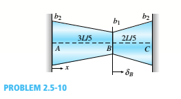
Chapter 2, Problem 2.5.10P
Repeat Problem 2.5-9 for the flat bar shown in the figure but assume that  and that
Expert Solution & Answer
Want to see the full answer?
Check out a sample textbook solution
Students have asked these similar questions
For the beam and loading shown, (a) draw the shear and bending moment diagrams, (b) determine the magnitude and location of the maximum absolute value of the bending momentConsider A = 0please show step by step process, i did something wrong with bending moment diagram( length of beam = 2 + 6 + 2)
CORRECT ANSWER ONLY WITH COMPLETE FBD. PREFERABLY HANDWRITTEN. I WILL UPVOTE
1. The beam shown carries the following loads:Total dead load, wDL = 36 kN/mConcentrated live load, PLL = 240 kNThe beam section is HSS16X12X3/8 with properties:Span, L = 6 mArea, A = 12,100 mm2Moment of inertia about x-axis, Ix = 292 x 106 mm4Fy = 345 MPa
1. Calculate the location of the live load, from the left support, for maximum moment to occur at the fixed support.Answer: 2.536 m2. Calculate the maximum moment. Answer: 439.128 kN-m
CORRECT ANSWER AND COMPLETE FBD ONLY. I PREFER HANDWRITTEN BUT ITS OKAY IF NOT. I WILL UPVOTE
2. The space truss shown is supported by ball-and-socket joints at A, B and C. Factored loads P1 and P2 areacting on joints D and E, respectively, towards the negative y-direction.
1. Calculate the stress of member CE, indicate tension or compression. Answer: 23.61 MPa Tension2. Calculate the stress of member AD, indicate tension or compression. Answer: 21.01 MPa Compression3. Calculate the stress of member CD, indicate tension or compression. Answer: 11.03 MPa Tension
Chapter 2 Solutions
Bundle: Mechanics Of Materials, Loose-leaf Version, 9th + Mindtap Engineering, 1 Term (6 Months) Printed Access Card
Ch. 2 - A 10-ft rigid bar AB is supported with a vertical...Ch. 2 - Rigid bar ABC is supported with a pin at A and an...Ch. 2 - The L-shaped arm ABCD shown in the figure lies in...Ch. 2 - A steel cable with a nominal diameter of 25 mm...Ch. 2 - A steel wire- and an aluminum allay wire have...Ch. 2 - By what distance h does the cage shown in the...Ch. 2 - Rigid bar ACB is supported by an elastic circular...Ch. 2 - A plastic cylinder is held snugly between a rigid...Ch. 2 - A safety valve on the top of a tank containing...Ch. 2 - The device shown in the figure consists of a...
Ch. 2 - A small lab scale has a rigid L-shaped frame ABC...Ch. 2 - A small lab scale has a rigid L-shaped frame ABC...Ch. 2 - Two rigid bars are connected to each other by two...Ch. 2 - The three-bar truss ABC shown in the figure part a...Ch. 2 - An aluminum wire having a diameter d = 1/10 in....Ch. 2 - A uniform bar AB of weight W = 25 N is supported...Ch. 2 - A hollow, circular, cast-iron pipe (Ec =12,000...Ch. 2 - The horizon Lai rigid beam A BCD is supported by...Ch. 2 - Two pipe columns (AB, FC) are pin-connected to a...Ch. 2 - A framework ABC consists of two rigid bars AB and...Ch. 2 - Solve the preceding problem for the following...Ch. 2 - The length of the end segments of the bar (see...Ch. 2 - A long, rectangular copper bar under a tensile...Ch. 2 - An aluminum bar AD (see figure) has a...Ch. 2 - A vertical bar consists of three prismatic...Ch. 2 - A vertical bar is loaded with axial loads at...Ch. 2 - Repeat Problem 2.3-4, but now include the weight...Ch. 2 - -7 Repeat Problem 2.3-5, but n include the weight...Ch. 2 - A rectangular bar of length L has a slot in the...Ch. 2 - Solve the preceding problem if the axial stress in...Ch. 2 - A two-story building has steel columns AB in the...Ch. 2 - A steel bar is 8.0 Ft long and has a circular...Ch. 2 - A bar ABC of length L consists of two parts of...Ch. 2 - A woodpile, driven into the earth, supports a load...Ch. 2 - Consider the copper lubes joined in the strength...Ch. 2 - The nonprismalic cantilever circular bar shown has...Ch. 2 - *16 A prismatic bar AB of length L,...Ch. 2 - A flat bar of rectangular cross section, length L,...Ch. 2 - A flat brass bar has length L, constant thickness...Ch. 2 - Repeat Problem 2.3-18, but assume that the bar is...Ch. 2 - Repeat Problem 2.3-18, but assume that the bar is...Ch. 2 - A slightly tapered bar AB of solid circular crass...Ch. 2 - A circular aluminum alloy bar of length L = 1.8 m...Ch. 2 - A long, slender bar in the shape of a right...Ch. 2 - A post AB supporting equipment in a laboratory is...Ch. 2 - The main cables of a suspension bridge (see figure...Ch. 2 - A uniformly tapered lube AB of circular cross...Ch. 2 - A vertical steel bar ABC is pin-supported at its...Ch. 2 - A T-frame structure is torn posed of a prismatic...Ch. 2 - A T-frame structure is composed of prismatic beam...Ch. 2 - Repeat Problem 2.3-29 if vertical load P at D is...Ch. 2 - A bar ABC revolves in a horizontal plane about a...Ch. 2 - The assembly shown in the figure consists of a...Ch. 2 - A cylindrical assembly consisting of a brass core...Ch. 2 - A steel bar with a uniform cross section, is fixed...Ch. 2 - A horizontal rigid bar ABC is pinned at end A and...Ch. 2 - A solid circular steel cylinder S is encased in a...Ch. 2 - Three prismatic bars, two of material A and one of...Ch. 2 - A circular bar ACB of a diameter d having a...Ch. 2 - Bar ABC is fixed at both ends (see figure) and has...Ch. 2 - Repeat Problem 2.4-8, but assume that the bar is...Ch. 2 - A plastic rod AB of length L = 0.5 m has a...Ch. 2 - 2.4-11 Three steel cables jointly support a load...Ch. 2 - The fixed-end bar ABCD consists of three prismatic...Ch. 2 - A lube structure is acted on by loads at B and D,...Ch. 2 - A hollow circular pipe (see figure} support s a...Ch. 2 - The aluminum and steel pipes shown in the figure...Ch. 2 - A rigid bar of weight W = SOO N hangs from three...Ch. 2 - A bimetallic bar (or composite bar) of square...Ch. 2 - S Three-bar truss ABC (see figure) is constructed...Ch. 2 - A horizontal rigid bar of weight If' = 72001b is...Ch. 2 - A rigid bar ABCD is pinned at point B and...Ch. 2 - A rigid bar AB if of a length B = 66 in. is....Ch. 2 - Find expressions For all support reaction forces...Ch. 2 - A trimetallic bar is uniformly compressed by an...Ch. 2 - Find expressions for all support reaction Forces...Ch. 2 - The rails of a railroad track are welded together...Ch. 2 - A circular steel rod of diameter d is subjected to...Ch. 2 - A rigid bar of weight W = 750 lb hangs from three...Ch. 2 - A steel rod. of 15-mm diameter is held snugly (but...Ch. 2 - A bar AB of length L is held between rigid...Ch. 2 - A beam is constructed using two angle sections (L...Ch. 2 - A W 8 × 28 beam of a length 10 ft is held between...Ch. 2 - A plastic bar ACB having two different solid...Ch. 2 - ,5-9 A flat aluminum alloy bar is fixed at both...Ch. 2 - Repeat Problem 2.5-9 for the flat bar shown in the...Ch. 2 - A circular steel rod AB? (diameter d, = 1.0 in.,...Ch. 2 - A circular, aluminum alloy bar of a length L = 1.8...Ch. 2 - Rectangular bars of copper and aluminum are held...Ch. 2 - A brass sleeve S is fitted over a steel bolt B...Ch. 2 - A rigid triangular frame is pivoted at C and held...Ch. 2 - ,5-16 A rigid bar ABCD is pinned at end A and...Ch. 2 - A copper bar AB with a length 25 in. and diameter...Ch. 2 - A steel wire AB is stretched between rigid...Ch. 2 - -19 The mechanical assembly shown in the figure...Ch. 2 - A bar AB having a length L and axial rigidity EA...Ch. 2 - Pipe 2 has been inserted snugly into Pipe I. but...Ch. 2 - A non prism elk- bar ABC made up of segments...Ch. 2 - Wires B and C are attached to a support at the...Ch. 2 - A rigid steel plate is supported by three posts of...Ch. 2 - A capped cast-iron pipe is compressed by a brass...Ch. 2 - A plastic cylinder is held snugly between a rigid...Ch. 2 - Prob. 2.5.27PCh. 2 - Consider the sleeve made From two copper tubes...Ch. 2 - A polyethylene tube (length L) has a cap that when...Ch. 2 - Prestressed concrete beams are sometimes...Ch. 2 - Prob. 2.5.31PCh. 2 - A steel bar of rectangular cross section (1.5 in....Ch. 2 - A circular steel rod of diameter d is subjected to...Ch. 2 - A standard brick (dimensions 8 in. × 4 in. × 2.5...Ch. 2 - A brass wire of diameter d = 2.42 mm is stretched...Ch. 2 - Prob. 2.6.5PCh. 2 - A steel bar with a diameter d = 12 mm is subjected...Ch. 2 - During a tension lest of a mild-steel specimen...Ch. 2 - A copper bar with a rectangular cross section is...Ch. 2 - A prismatic bar with a length L = 3 ft and...Ch. 2 - A prismatic bar with a length L = 1 m and...Ch. 2 - The plane truss in the figure is assembled From...Ch. 2 - Plastic bar of diameter d = 32 mm is compressed in...Ch. 2 - A plastic bar of rectangular cross section (ft =...Ch. 2 - A copper bar of rectangular cross section (b = 18...Ch. 2 - A circular brass bar with a diameter J is member...Ch. 2 - Two boards are joined by gluing along a scarf...Ch. 2 - Acting on the sides of a stress element cut from a...Ch. 2 - A prismatic bar is subjected to an axial force...Ch. 2 - The normal stress on plane pq of a prismatic bar...Ch. 2 - A tension member is to be constructed of two...Ch. 2 - -21 Plastic bar AB of rectangular cross section (6...Ch. 2 - A compression bar having a square cross section...Ch. 2 - A prismatic bar AD of length L, cross-sectional...Ch. 2 - A bar with a circular cross section having two...Ch. 2 - A three-story steel column in a building supports...Ch. 2 - The bar ABC shown in the figure is loaded by a...Ch. 2 - Determine the strain energy per unit volume (units...Ch. 2 - The truss ABC shown in the Figure is subjected to...Ch. 2 - -7 The truss A BC Shawn in the figure supports a...Ch. 2 - The statically indeterminate structure shown in...Ch. 2 - A slightly tapered bar AB of rectangular cross...Ch. 2 - A compressive load P is transmitted through a...Ch. 2 - A block B is pushed against three springs by a...Ch. 2 - A bungee cord that behaves linearly elastically...Ch. 2 - A sliding collar of weight W = 150 lb falls From a...Ch. 2 - Solve the preceding problem if the collar has mass...Ch. 2 - Prob. 2.8.3PCh. 2 - A block weighing W = 5.0 N drops inside a cylinder...Ch. 2 - Solve the preceding problem for W = 1.0 lb. h = 12...Ch. 2 - Prob. 2.8.6PCh. 2 - A weight W = 4500 lb falls from a height h onto a...Ch. 2 - Prob. 2.8.8PCh. 2 - Prob. 2.8.9PCh. 2 - A bumping post at the end of a track in a railway...Ch. 2 - A bumper for a mine car is constructed with a...Ch. 2 - A bungee jumper having a mass of 55 kg leaps from...Ch. 2 - Prob. 2.8.13PCh. 2 - A rigid bar AB having a mass M = 1.0 kg and length...Ch. 2 - The flat bars shown in parts a and b of the figure...Ch. 2 - The flat bars shown in parts a and b of the figure...Ch. 2 - A flat bar of width b and thickness t has a hole...Ch. 2 - Around brass bar of a diameter d1= 20mm has upset...Ch. 2 - Prob. 2.10.5PCh. 2 - ,10-6 A prismatic bar with a diameter d0= 20 mm is...Ch. 2 - A stepped bar with a hole (see figure) has widths...Ch. 2 - A bar AB of length L and weight density y hangs...Ch. 2 - A prismatic bar of length L = 1.8 m and...Ch. 2 - Prob. 2.11.3PCh. 2 - A prismatic bar in tension has a length L = 2.0 m...Ch. 2 - An aluminum bar subjected to tensile Forces P has...Ch. 2 - A rigid bar AB is pinned al end A and is supported...Ch. 2 - Two identical bars AB and BC support a vertical...Ch. 2 - A stepped bar ACB with circular cross sections is...Ch. 2 - A horizontal rigid bar AB supporting a load P is...Ch. 2 - Prob. 2.12.4PCh. 2 - The symmetric truss ABCDE shown in the figure is...Ch. 2 - Five bars, each having a diameter of 10 mm....Ch. 2 - Prob. 2.12.7PCh. 2 - A rigid bar ACB is supported on a fulcrum at C and...Ch. 2 - The structure shown in the figure consists of a...Ch. 2 - Two cables, each having a length i. of...Ch. 2 - A hollow circular tube T of a length L = 15 in. is...
Knowledge Booster


Learn more about
Need a deep-dive on the concept behind this application? Look no further. Learn more about this topic, mechanical-engineering and related others by exploring similar questions and additional content below.Similar questions
- CORRECT ANSWER AND COMPLETE FBD ONLY. I PREFER HANDWRITTEN BUT ITS OKAY IF NOT. I WILL UPVOTE 3. The frame has pin supports at A and E, subject to a wind load. Treat joint C to be an internal hinge. Given:Dimensions, H1 = 3.0 m; H2 = 4.5 m; L = 10.0 mWind loads, wWL (AB) = 4.8 kN/m; wWL (BC) = 3.9 kN/m; wWL (CD) = 1.5 kN/m; wWL (DE) = 1.2 kN/mMembers are made of A36 steel Wide Flange Section with the following properties:Area, A = 64000 mm2Depth, d = 762 mmFlange width, bf = 371 mmThickness of web, tw = 32 mmThickness of flange, tf = 57.9 mmMoment of inertia about x-axis, Ix = 6080 x 106 mm4The wide flange is oriented so that the bending is about the x-axis1. Calculate the stress in member AB, due to the axial load it carries, indicate if tension or compression.Answer: 0.0476 MPa Tension2. Calculate the stress in member DE, due to the axial load it carries, indicate if tension or compression.Answer: 0.2351 MPa Compression3. Calculate the maximum bending stress at B. Answer: 4.282 MPaarrow_forward32 mm 32 mm b' c' C 32 mm 32 mm b PROBLEM 6.41 a The extruded beam shown has a uniform wall thickness of 3 mm. Knowing that the vertical shear in the beam is 9 kN, determine the shearing stress at each of the five points indicated.arrow_forwardIn a structural reliability problem, the resistance (capacity) R and load effect (demand) S random variables associated with a failure mode of the structure of interest are normally distributed and statistically independent with the following probability distribution parameters (or statistics) in consistent units: MR = 12, σR = 3 μs = 5, σs = 2 (a) Determine the exact probability of failure pF ·arrow_forward
- The resistance R and load effect S for a given failure mode are statistically independent random variables with marginal PDF's 1 fR (r) = 0≤r≤100 100' fs(s)=0.05e-0.05s (a) Determine the probability of failure by computing the probability content of the failure domain defined as {rarrow_forwardPlease solve this problem as soon as possible My ID# 016948724arrow_forwardThe gears shown in the figure have a diametral pitch of 2 teeth per inch and a 20° pressure angle. The pinion rotates at 1800 rev/min clockwise and transmits 200 hp through the idler pair to gear 5 on shaft c. What forces do gears 3 and 4 transmit to the idler shaft? TS I y 18T 32T This a 12 x 18T C 48T 5arrow_forwardQuestion 1. Draw 3 teeth for the following pinion and gear respectively. The teeth should be drawn near the pressure line so that the teeth from the pinion should mesh those of the gear. Drawing scale (1:1). Either a precise hand drawing or CAD drawing is acceptable. Draw all the trajectories of the involute lines and the circles. Specification: 18tooth pinion and 30tooth gear. Diameter pitch=P=6 teeth /inch. Pressure angle:20°, 1/P for addendum (a) and 1.25/P for dedendum (b). For fillet, c=b-a.arrow_forward5. The figure shows a gear train. There is no friction at the bearings except for the gear tooth forces. The material of the milled gears is steel having a Brinell hardness of 170. The input shaft speed (n2) is 800 rpm. The face width and the contact angle for all gears are 1 in and 20° respectively. In this gear set, the endurance limit (Se) is 15 kpsi and nd (design factor) is 2. (a) Find the revolution speed of gear 5. (b) Determine whether each gear satisfies the design factor of 2.0 for bending fatigue. (c) Determine whether each gear satisfies the design factor of 2.0 for surface fatigue (contact stress). (d) According to the computation results of the questions (b) and (c), explain the possible failure mechanisms for each gear. N4=28 800rpm N₁=43 N5=34 N₂=14 P(diameteral pitch)=8 for all gears Coupled to 2.5hp motorarrow_forward1. The rotating steel shaft is simply supported by bearings at points of B and C, and is driven by a spur gear at D, which has a 6-in pitch diameter. The force F from the drive gear acts at a pressure angle of 20°. The shaft transmits a torque to point A of TA =3000 lbĘ in. The shaft is machined from steel with Sy=60kpsi and Sut=80 kpsi. (1) Draw a shear force diagram and a bending moment diagram by F. According to your analysis, where is the point of interest to evaluate the safety factor among A, B, C, and D? Describe the reason. (Hint: To find F, the torque Tд is generated by the tangential force of F (i.e. Ftangential-Fcos20°) When n=2.5, K=1.8, and K₁ =1.3, determine the diameter of the shaft based on (2) static analysis using DE theory (note that fatigue stress concentration factors need to be used for this question because the loading condition is fatigue) and (3) a fatigue analysis using modified Goodman. Note) A standard diameter is not required for the questions. 10 in Darrow_forward3 N2=28 P(diametral pitch)=8 for all gears Coupled to 25 hp motor N3=34 Full depth spur gears with pressure angle=20° N₂=2000 rpm (1) Compute the circular pitch, the center-to-center distance, and base circle radii. (2) Draw the free body diagram of gear 3 and show all the forces and the torque. (3) In mounting gears, the center-to-center distance was reduced by 0.1 inch. Calculate the new values of center-to-center distance, pressure angle, base circle radii, and pitch circle diameters. (4)What is the new tangential and radial forces for gear 3? (5) Under the new center to center distance, is the contact ratio (mc) increasing or decreasing?arrow_forward2. A flat belt drive consists of two 4-ft diameter cast-iron pulleys spaced 16 ft apart. A power of 60 hp is transmitted by a pulley whose speed is 380 rev/min. Use a service factor (Ks) pf 1.1 and a design factor 1.0. The width of the polyamide A-3 belt is 6 in. Use CD=1. Answer the following questions. (1) What is the total length of the belt according to the given geometry? (2) Find the centrifugal force (Fc) applied to the belt. (3) What is the transmitted torque through the pulley system given 60hp? (4) Using the allowable tension, find the force (F₁) on the tight side. What is the tension at the loose side (F2) and the initial tension (F.)? (5) Using the forces, estimate the developed friction coefficient (f) (6) Based on the forces and the given rotational speed, rate the pulley set. In other words, what is the horse power that can be transmitted by the pulley system? (7) To reduce the applied tension on the tight side, the friction coefficient is increased to 0.75. Find out the…arrow_forwardThe tooth numbers for the gear train illustrated are N₂ = 24, N3 = 18, №4 = 30, №6 = 36, and N₁ = 54. Gear 7 is fixed. If shaft b is turned through 5 revolutions, how many turns will shaft a make? a 5 [6] barrow_forwardarrow_back_iosSEE MORE QUESTIONSarrow_forward_ios
Recommended textbooks for you
 Mechanics of Materials (MindTap Course List)Mechanical EngineeringISBN:9781337093347Author:Barry J. Goodno, James M. GerePublisher:Cengage Learning
Mechanics of Materials (MindTap Course List)
Mechanical Engineering
ISBN:9781337093347
Author:Barry J. Goodno, James M. Gere
Publisher:Cengage Learning
Solids: Lesson 53 - Slope and Deflection of Beams Intro; Author: Jeff Hanson;https://www.youtube.com/watch?v=I7lTq68JRmY;License: Standard YouTube License, CC-BY