
Concept explainers
Calculate the hydrodynamic load applied at floor level on the wall IJKL due to outflow for load cases 2 and 3.
Calculate the hydrostatic loading on the adjacent outside walls due to water retained by the floor and the debris impact load applied to the free standing column CD.
Answer to Problem 22P
The hydrodynamic load applied at floor level on the wall IJKL due to outflow for load case 2 is
The hydrodynamic load applied at floor level on the wall IJKL at J due to outflow for load case 3 is
The hydrodynamic load applied at floor level on the wall IJKL at K due to outflow for load case 3 is
The hydrostatic loading on the adjacent outside walls due to water retained by the floor is
Explanation of Solution
Given information:
The width of the building (B) is 35 ft.
The maximum inundation height
The flow velocity
Assume
Calculation:
For load case 2:
Calculate the height of the water applicable to the structure
Calculate the velocity of flow applicable to the structure
Sketch the load applied at floor level on the wall IJKL due to outflow for load case 2 as shown in Figure 1.
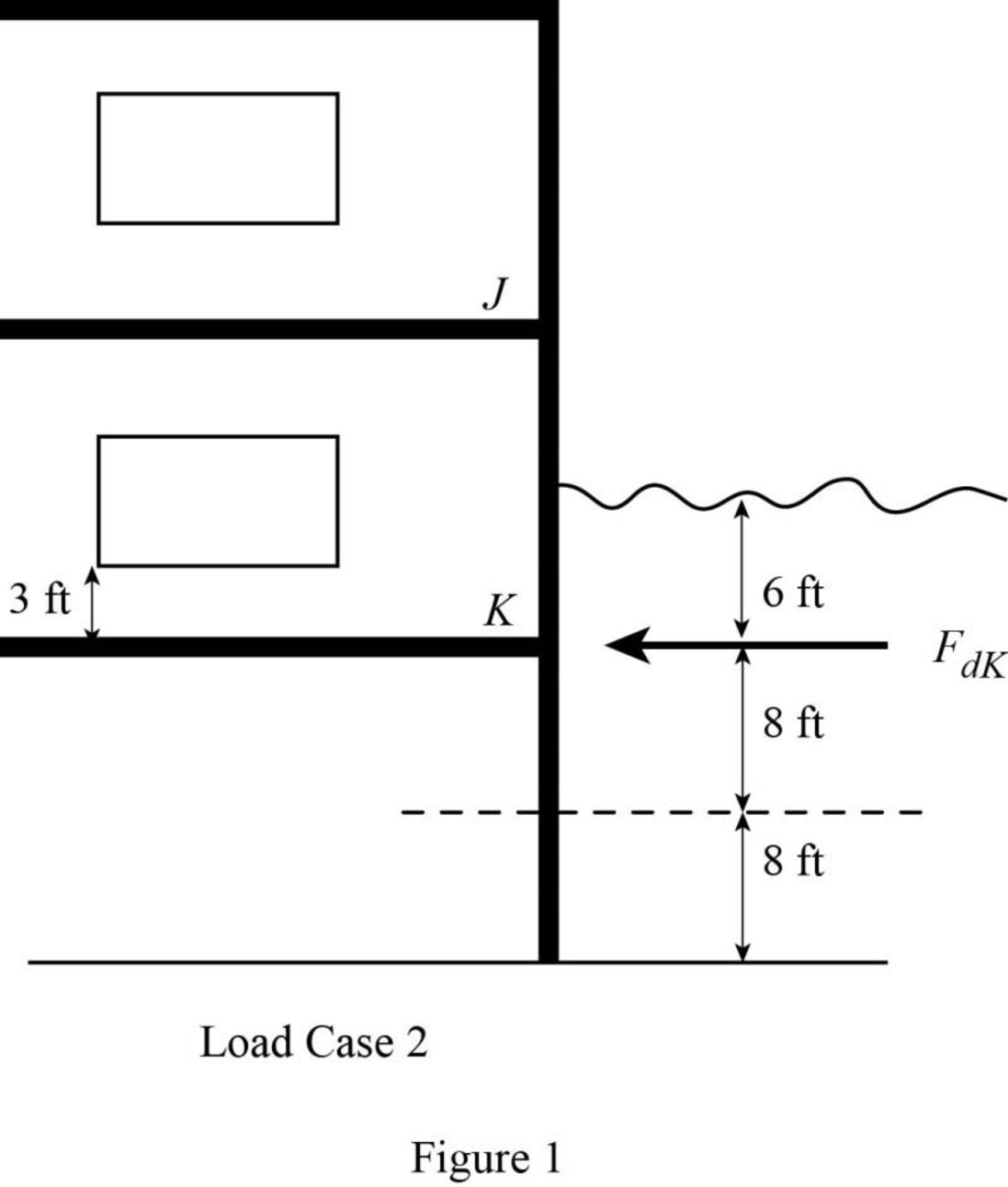
Refer to Figure 1.
Calculate the height of the water applicable to the structure for K as shown below.
Consider the specific weight density of sea water
Calculate the hydrodynamic load applied at floor level on the wall IJKL
Hence, the hydrodynamic load applied at floor level on the wall IJKL due to outflow for load case 2 is
For load case 3:
Calculate the height of the water applicable to the structure
Calculate the velocity of flow applicable to the structure
Sketch the load applied at floor level on the wall IJKL due to outflow for load case 3 as shown in Figure 2.
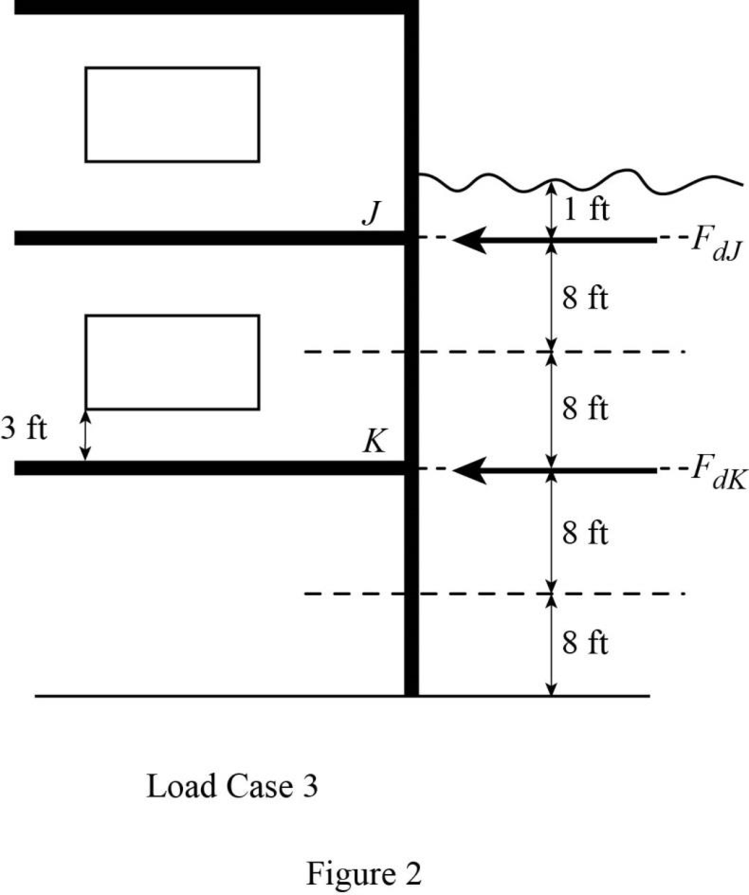
Refer to Figure 2.
Calculate the height of the water applicable to the structure for J as shown below.
Calculate the hydrodynamic load applied at floor level on the wall IJKL at J
Hence, the hydrodynamic load applied at floor level on the wall IJKL at J due to outflow for load case 3 is
Calculate the height of the water applicable to the structure for K as shown below.
Calculate the hydrodynamic load applied at floor level on the wall IJKL at K
Hence, the hydrodynamic load applied at floor level on the wall IJKL at K due to outflow for load case 3 is
Sketch the hydrostatic loading on the adjacent outside walls due to water retained by the floor as shown in Figure 3.
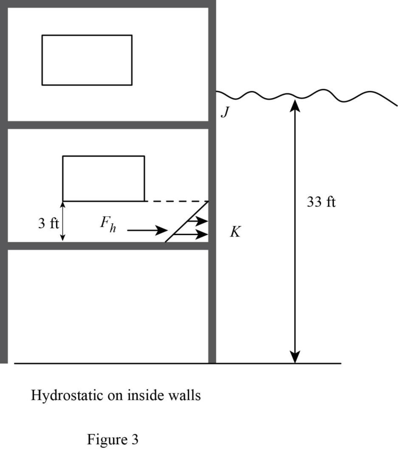
Refer to Figure 3.
Calculate the height of the water applicable to the structure
Calculate the hydrostatic loading on the adjacent outside walls due to water retained by the floor as shown below.
Hence, the hydrostatic loading on the adjacent outside walls due to water retained by the floor is
Consider the orientation coefficient
Calculate the debris impact load applied to the free standing column CD as shown below.
Therefore, the debris impact load applied to the free standing column CD is
Want to see more full solutions like this?
Chapter 2 Solutions
Fundamentals Of Structural Analysis:


- -The axial deflection pipe in inches. -The lateral deflection of the beam in inches -The total deflection of the beam like structure in inches ? all to 4 sig figs AI did not help. as i input what i get im not sure if its a rounding error or what.arrow_forward1. For the foundation shown below: Qapp = 60 kips (Load obtained from structural engineer) 1.5 ft G.W.T. 3 ft Poorly Graded Sand (SP): Ym 115 pcf (above G.W.T.) Ysat 125 pcf (below G.W.T.) c' = 0, ' = 35° K Square footing, 4' x 4' Foundation Dimension Information: 1-ft x 1-ft square concrete column. 1-ft thick "foot" flanges. Yconc=150 pcf *Assume weight of reinforcing steel included in unit weight of concrete. *Assume compacted backfill weighs the same as in-situ soil. Assume this foundation is being designed for a warehouse that had a thorough preliminary soil exploration. Using the general bearing capacity equation: a. Calculate the gross applied bearing pressure, the gross ultimate bearing pressure, and determine if the foundation system is safe using a gross bearing capacity ASD approach. Please include the weight of the foundation, the weight of the backfill soil, and the effect of the uplift pressure caused by the presence of the water table in your bearing capacity…arrow_forward٢٥ ٠٥:٤٠١٠ 2025 ChatGPT VivaCut Onet Puzzle مسلم X Excel JPG I❤> PDF Copilot Chat Bot PDF2IMG iLovePDF NokoPrint O.O StudyX ☑ W CapCut Candy Crush DeepSeek Word ☐ Saga 啡 AcadAl ل TikTokarrow_forward
- Refer to the figure below. Given: L = 7 m, y = 16.7 kN/m², and ø' = 30°. L L3 ση Sand γ $' D T LA L σε σε IN P Sand 1. Calculate the theoretical depth of penetration, D. (Enter your answer to three significant figures.) D= m 2. Calculate the maximum moment. (Enter your answer to three significant figures.) Mmax kN-m/marrow_forwardWhy is it important for construction project managers to be flexible when dealing with the many variable factors that pop up in a project?arrow_forwardWhat are some reasons for why a company would accelerate a construction project?arrow_forward
- For the design of a shallow foundation, given the following: Soil: ' = 20° c' = 52 kN/m² Unit weight, y = 15 kN/m³ Modulus of elasticity, E, = 1400 kN/m² Poisson's ratio, μs = 0.35 Foundation: L=2m B=1m Df = 1 m Calculate the ultimate bearing capacity. Use the equation: 1 - qu = c' NcFcs Fcd Fcc +qNqFqsFqdFqc + ½√BN√Fãs F√dƑxc 2 For '=20°, Nc = 14.83, N₁ = 6.4, and N₁ = 5.39. (Enter your answer to three significant figures.) qu = kN/m²arrow_forwardA 2.0 m wide strip foundation carries a wall load of 350 kN/m in a clayey soil where y = 15 kN/m³, c' = 5.0 kN/m² and ' = 23°. The foundation depth is 1.5 m. For ' = 23°: Nc = 18.05; N₁ = 8.66; Ny = = = 8.20. Determine the factor of safety using the equation below. qu= c' NcFcs FcdFci+qNqFqsFq 1 F + gd. 'qi 2 ·BN√· FF γί Ysyd F (Enter your answer to three significant figures.) FS =arrow_forward2P -1.8 m- -1.8 m- -B Wo P -1.8 m- Carrow_forward
- Part F: Progressive activity week 7 Q.F1 Pick the rural location of a project site in Victoria, and its catchment area-not bigger than 25 sqkm, and given the below information, determine the rainfall intensity for ARI 5, 50, 100 year storm event. Show all the details of the procedure. Each student must propose different length of streams and elevations. Use fig below as a sample only. Pt. E-nt 950 200 P: D-40, PC-92.0 300m 300m 000m PL.-02.0 500m HI-MAGO PLA-M 91.00 To be deemed satisfactory the solution must include: Q.F1.1.Choice of catchment location Q.F1.2. A sketch displaying length of stream and elevation Q.F1.3. Catchment's IFD obtained from the Buro of Metheorology for specified ARI Q.F1.4.Calculation of the time of concentration-this must include a detailed determination of the equivalent slope. Q.F1.5.Use must be made of the Bransby-Williams method for the determination of the equivalent slope. Q.F1.6.The graphical display of the estimation of intensities for ARI 5,50, 100…arrow_forwardI need help finding: -The axial deflection pipe in inches. -The lateral deflection of the beam in inches -The total deflection of the beam like structure in inches ?arrow_forwardA 2.0 m wide strip foundation carries a wall load of 350 kN/m in a clayey soil where y = 17 kN/m³, c' = 5.0 kN/m² and 23°. The foundation depth is 1.5 m. For o' = 23°: Nc = 18.05; N = 8.66; N = 8.20. Determine the factor of safety using the equation below. 1 qu = c' NcFcs Fed Fci +qNqFqs FqdFqi + ½ BN F√s 1 2 (Enter your answer to three significant figures.) s Fyd Fi FS =arrow_forward

 Structural Analysis (10th Edition)Civil EngineeringISBN:9780134610672Author:Russell C. HibbelerPublisher:PEARSON
 Principles of Foundation Engineering (MindTap Cou...Civil EngineeringISBN:9781337705028Author:Braja M. Das, Nagaratnam SivakuganPublisher:Cengage Learning
 Fundamentals of Structural AnalysisCivil EngineeringISBN:9780073398006Author:Kenneth M. Leet Emeritus, Chia-Ming Uang, Joel LanningPublisher:McGraw-Hill Education
 Traffic and Highway EngineeringCivil EngineeringISBN:9781305156241Author:Garber, Nicholas J.Publisher:Cengage Learning