EBK MACHINE ELEMENTS IN MECHANICAL DESI
6th Edition
ISBN: 9780134451947
Author: Wang
Publisher: YUZU
expand_more
expand_more
format_list_bulleted
Videos
Textbook Question
Chapter 2, Problem 1P
Define ultimate tensile strength.
Expert Solution & Answer
To determine
To define:The ultimate tensile strength.
Explanation of Solution
Ultimate tensile strength:
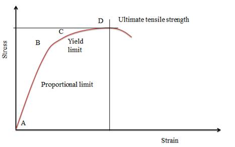
The ultimate tensile strength is defined as the maximum allowable strength for any material without breaking under the application of load. It is also called tensile strength. This is the maximum stress in the stress-strain curve. Thus, ultimate strength is the extreme stress that material can bear.
As shown in the figure below stress-strain curve for the materials. In the above figure, the AB represents the proportional limit, BC represents the yield limit, and D denotes the (UTS) Ultimate tensile strength. After point D, the material will go under fracture, as shown in the figure.
Want to see more full solutions like this?
Subscribe now to access step-by-step solutions to millions of textbook problems written by subject matter experts!
Students have asked these similar questions
PROBLEM 3.23
3.23 Under normal operating condi-
tions a motor exerts a torque of
magnitude TF at F. The shafts
are made of a steel for which
the allowable shearing stress is
82 MPa and have diameters of
dCDE=24 mm and dFGH = 20
mm. Knowing that rp = 165
mm and rg114 mm, deter-
mine the largest torque TF
which may be exerted at F.
TF
F
rG-
rp
B
CH
TE
E
1. (16%) (a) If a ductile material fails under pure torsion, please explain the failure
mode and describe the observed plane of failure.
(b) Suppose a prismatic beam is subjected to equal and opposite couples as shown
in Fig. 1. Please sketch the deformation and the stress distribution of the cross
section.
M
M
Fig. 1
(c) Describe the definition of the neutral axis.
(d) Describe the definition of the modular ratio.
using the theorem of three moments, find all the moments, I only need concise calculations with minimal explanations. The correct answers are provided at the bottom
Chapter 2 Solutions
EBK MACHINE ELEMENTS IN MECHANICAL DESI
Ch. 2 - Define ultimate tensile strength.Ch. 2 - Define yield point.Ch. 2 - Define yield strength and tell how it is measured.Ch. 2 - What types of materials would have a yield point?Ch. 2 - What is the difference between proportional limit...Ch. 2 - Define Hooke’s law.Ch. 2 - What property of a material is a measure of its...Ch. 2 - What property of a material is a measure of its...Ch. 2 - If a material is reported to have a percent...Ch. 2 - Define Poisson’s ratio.
Ch. 2 - If a material has a tensile modulus of elasticity...Ch. 2 - A material is reported to have a Brinell hardness...Ch. 2 - A steel is reported to have a Brinell hardness of...Ch. 2 - For Problems 14 17, describe what is wrong with...Ch. 2 - For Problems 14 17, describe what is wrong with...Ch. 2 - For Problems 14 17, describe what is wrong with...Ch. 2 - For Problems 14 17, describe what is wrong with...Ch. 2 - Name two tests used to measure impact energy.Ch. 2 - Prob. 19PCh. 2 - Prob. 20PCh. 2 - Prob. 21PCh. 2 - What is the typical carbon content of a low-carbon...Ch. 2 - How much carbon does a bearing steel typically...Ch. 2 - What is the main difference between SAE 1213 steel...Ch. 2 - Name four materials that are commonly used for...Ch. 2 - Name four materials that are typically used for...Ch. 2 - Describe the properties desirable for the auger...Ch. 2 - Prob. 28PCh. 2 - Appendix 3If a shovel blade is made from SAE 1040...Ch. 2 - Describe the differences between through-hardening...Ch. 2 - Describe the process of induction hardening.Ch. 2 - Prob. 32PCh. 2 - Prob. 33PCh. 2 - Prob. 34PCh. 2 - Prob. 35PCh. 2 - Prob. 36PCh. 2 - Name three types of cast iron.Ch. 2 - Prob. 38PCh. 2 - Describe the process of making parts from powdered...Ch. 2 - Prob. 40PCh. 2 - Prob. 41PCh. 2 - Prob. 42PCh. 2 - Prob. 43PCh. 2 - Prob. 44PCh. 2 - Prob. 45PCh. 2 - Prob. 46PCh. 2 - Name three typical uses for titanium alloys.Ch. 2 - Prob. 48PCh. 2 - Prob. 49PCh. 2 - Prob. 50PCh. 2 - Describe the difference between thermosetting...Ch. 2 - Suggest a suitable plastic material for each of...Ch. 2 - Name eight factors over which the designer has...Ch. 2 - Define the term composite.Ch. 2 - Prob. 55PCh. 2 - Name four types of reinforcement fibers used for...Ch. 2 - Prob. 57PCh. 2 - Prob. 58PCh. 2 - Prob. 59PCh. 2 - For what applications are sheet-molding compounds...Ch. 2 - Prob. 61PCh. 2 - Prob. 62PCh. 2 - Prob. 63PCh. 2 - Prob. 64PCh. 2 - Prob. 65PCh. 2 - Prob. 66PCh. 2 - Prob. 67PCh. 2 - Prob. 68PCh. 2 - Discuss the advantages of composite materials...Ch. 2 - Prob. 70PCh. 2 - Prob. 71PCh. 2 - Prob. 72PCh. 2 - Prob. 73PCh. 2 - Describe the general construction of a composite...Ch. 2 - Prob. 75PCh. 2 - Prob. 76PCh. 2 - Prob. 77PCh. 2 - Prob. 78PCh. 2 - Prob. 79PCh. 2 - Prob. 80PCh. 2 - Prob. 81PCh. 2 - Prob. 82PCh. 2 - Prob. 83PCh. 2 - Problems 8290. For composites made with the given...Ch. 2 - Prob. 85PCh. 2 - Prob. 86PCh. 2 - Prob. 87PCh. 2 - Prob. 88PCh. 2 - Prob. 89PCh. 2 - Prob. 90PCh. 2 - Prob. 91PCh. 2 - Prob. 92PCh. 2 - Prob. 93PCh. 2 - Problems 94 96. For the given specification for a...Ch. 2 - Prob. 95PCh. 2 - Prob. 96PCh. 2 - Prob. 97PCh. 2 - Prob. 98PCh. 2 - Prob. 99PCh. 2 - Describe how CNTs are used in a CMNC and what...Ch. 2 - Prob. 1SPCh. 2 - Prob. 2SPCh. 2 - Prob. 3SPCh. 2 - Prob. 4SPCh. 2 - Prob. 5SPCh. 2 - Prob. 6SPCh. 2 - Name three U.S. organizations whose names are...Ch. 2 - Prob. 8SPCh. 2 - A U.S. designer specifies SAE 4140 steel for a...Ch. 2 - Prob. 10SPCh. 2 - Prob. 11SPCh. 2 - Prob. 12SPCh. 2 - Prob. 13SPCh. 2 - Prob. 14SPCh. 2 - Prob. 15SPCh. 2 - Prob. 16SPCh. 2 - Prob. 17SPCh. 2 - Prob. 18SPCh. 2 - Prob. 19SPCh. 2 - Prob. 20SPCh. 2 - Prob. 21SPCh. 2 - Prob. 22SPCh. 2 - Prob. 23SPCh. 2 - Prob. 24SPCh. 2 - Prob. 25SPCh. 2 - Prob. 26SPCh. 2 - Prob. 27SPCh. 2 - Prob. 28SPCh. 2 - Prob. 29SPCh. 2 - Prob. 30SPCh. 2 - Prob. 31SPCh. 2 - Prob. 32SPCh. 2 - Prob. 33SPCh. 2 - Prob. 34SPCh. 2 - List the six general classifications of materials...Ch. 2 - Prob. 36SPCh. 2 - Prob. 37SPCh. 2 - Prob. 38SPCh. 2 - Prob. 39SPCh. 2 - Prob. 40SP
Knowledge Booster


Learn more about
Need a deep-dive on the concept behind this application? Look no further. Learn more about this topic, mechanical-engineering and related others by exploring similar questions and additional content below.Similar questions
- PROBLEM 3.46 The solid cylindrical rod BC of length L = 600 mm is attached to the rigid lever AB of length a = 380 mm and to the support at C. When a 500 N force P is applied at A, design specifications require that the displacement of A not exceed 25 mm when a 500 N force P is applied at A For the material indicated determine the required diameter of the rod. Aluminium: Tall = 65 MPa, G = 27 GPa. Aarrow_forwardFind the equivalent mass of the rocker arm assembly with respect to the x coordinate. k₁ mi m2 k₁arrow_forward2. Figure below shows a U-tube manometer open at both ends and containing a column of liquid mercury of length l and specific weight y. Considering a small displacement x of the manometer meniscus from its equilibrium position (or datum), determine the equivalent spring constant associated with the restoring force. Datum Area, Aarrow_forward
- 1. The consequences of a head-on collision of two automobiles can be studied by considering the impact of the automobile on a barrier, as shown in figure below. Construct a mathematical model (i.e., draw the diagram) by considering the masses of the automobile body, engine, transmission, and suspension and the elasticity of the bumpers, radiator, sheet metal body, driveline, and engine mounts.arrow_forward3.) 15.40 – Collar B moves up at constant velocity vB = 1.5 m/s. Rod AB has length = 1.2 m. The incline is at angle = 25°. Compute an expression for the angular velocity of rod AB, ė and the velocity of end A of the rod (✓✓) as a function of v₂,1,0,0. Then compute numerical answers for ȧ & y_ with 0 = 50°.arrow_forward2.) 15.12 The assembly shown consists of the straight rod ABC which passes through and is welded to the grectangular plate DEFH. The assembly rotates about the axis AC with a constant angular velocity of 9 rad/s. Knowing that the motion when viewed from C is counterclockwise, determine the velocity and acceleration of corner F.arrow_forward
arrow_back_ios
SEE MORE QUESTIONS
arrow_forward_ios
Recommended textbooks for you
 Welding: Principles and Applications (MindTap Cou...Mechanical EngineeringISBN:9781305494695Author:Larry JeffusPublisher:Cengage Learning
Welding: Principles and Applications (MindTap Cou...
Mechanical Engineering
ISBN:9781305494695
Author:Larry Jeffus
Publisher:Cengage Learning
Introduction to Ferrous and Non-Ferrous Metals.; Author: Vincent Ryan;https://www.youtube.com/watch?v=zwnblxXyERE;License: Standard Youtube License